Figure 2-3 Block diagram for the working principle of the PIU
Board in-position module
Communication unit
module
Backplane
Inter-board
communication bus
Surge protection and failure
detection module
-48 V/-60 V
Board in-position
signals
Slot ID signals
CXP
CXP
CXP
Each board
Surge protection failure alarm signals
Slot ID module
Surge Protection and Failure Detection Module
This module protects the equipment against lightning and detects the failure of the anti-lightning
circuit. If the surge protection fails, the PIU reports the alarm signals to the AND1CXPA/
AND1CXPB.
Communication Unit Module
This module has the function of reporting the board manufacturing information, PCB version
information, and alarm signals about the surge protection failure.
Slot ID Module
This module reports the slot ID information to the AND1CXPA/AND1CXPB.
Board In-Position Module
This module reports the board in-position signals to the AND1CXPA/AND1CXPB.
2.2.4 Front Panel
On the front panel of the PIU, there are indicators, power supply interfaces, and a label.
Appearance of the Front Panel
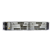
Figure 2-4 shows the appearance of the front panel of the PIU.
ATN 950B Multi-service Access Equipment
Hardware Description 2 Power Supply System
Issue 03 (2012-07-23) Huawei Proprietary and Confidential
Copyright © Huawei Technologies Co., Ltd.
12
 Loading...
