Clock Module
This module performs the following functions:
l When used with the AND1CXPA/AND1CXPB, processes the recovered line clock.
l Provides the working clock for each module on the board.
Power Supply Module
This module converts the input DC voltage into various DC voltages required by each module
on the board.
5.8.4 Front Panel
On the front panel of the AND2MD1A/AND2MD1B, there are indicators and interfaces.
Appearances of the Front Panel
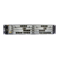
Figure 5-17 shows the appearances of the front panel of the AND2MD1A/AND2MD1B.
Figure 5-17 Front panels of the AND2MD1A/AND2MD1B
Indicators
The following indicators are present on the front panel of the AND2MD1A/AND2MD1B:
l STAT indicator, red, green, or orange, which indicates the working status
For details on meanings of indicators, see 11 Indicators.
Interfaces
There are two Anea 96 interfaces on the front panel of the AND2MD1A/AND2MD1B. Table
5-30 lists the type and usage of the interfaces. 9.4.2 75-Ohm 16 x E1 Cables and 9.4.3 120-
Ohm 16 x E1 Cables list the cables corresponding to the interfaces.
ATN 950B Multi-service Access Equipment
Hardware Description 5 Physical Interface Card
Issue 03 (2012-07-23) Huawei Proprietary and Confidential
Copyright © Huawei Technologies Co., Ltd.
78
 Loading...
