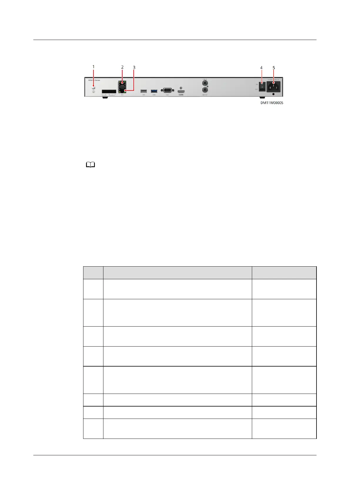
Figure 4-62 Ports on the VCN
(1) Ground terminal (2) GE1 port (3) GE2 port
(4) Power button (5) Power port
Step 3 Connect one end of the power cable to the input power port on the power module
and the other end to the PDU2000 in the cabinet.
After connecting the power cable, turn on the power switch on the panel to start the
device.
----End
4.4 Verifying the Installation
Cabinet Installation Check
Table 4-8 Cabinet installation check items
No.
Check That Check Result
1 The cabinet position is consistent with the
equipment room layout diagram.
□ Passed □ Failed
2 All bolts are tightened, especially the bolts used
for electric connection. Flat washers and spring
washers are installed properly.
□ Passed □ Failed
3 The cabinet is clean and free of dust and other
materials.
□ Passed □ Failed
4 The cabinet is clean and complies with dustproof
requirements.
□ Passed □ Failed
5 The paint on the cabinet exterior is intact.
Promptly repaint the cabinet exterior if necessary
to prevent corrosion.
□ Passed □ Failed
6 The cabinet door and lock work properly. □ Passed □ Failed
7 All labels are correct, clear, and complete. □ Passed □ Failed
8 The cabinet has no waste tape, cable ties, paper,
or packing materials around it.
□ Passed □ Failed
FusionModule500 Smart Mini Data Center
User Manual (Philippines, FusionModule500-
SU61A12S) 4 Installation Guide
Issue 02 (2021-06-30) Copyright © Huawei Technologies Co., Ltd. 99