Running/Alarm Indicators on a 6 U Controller Enclosure
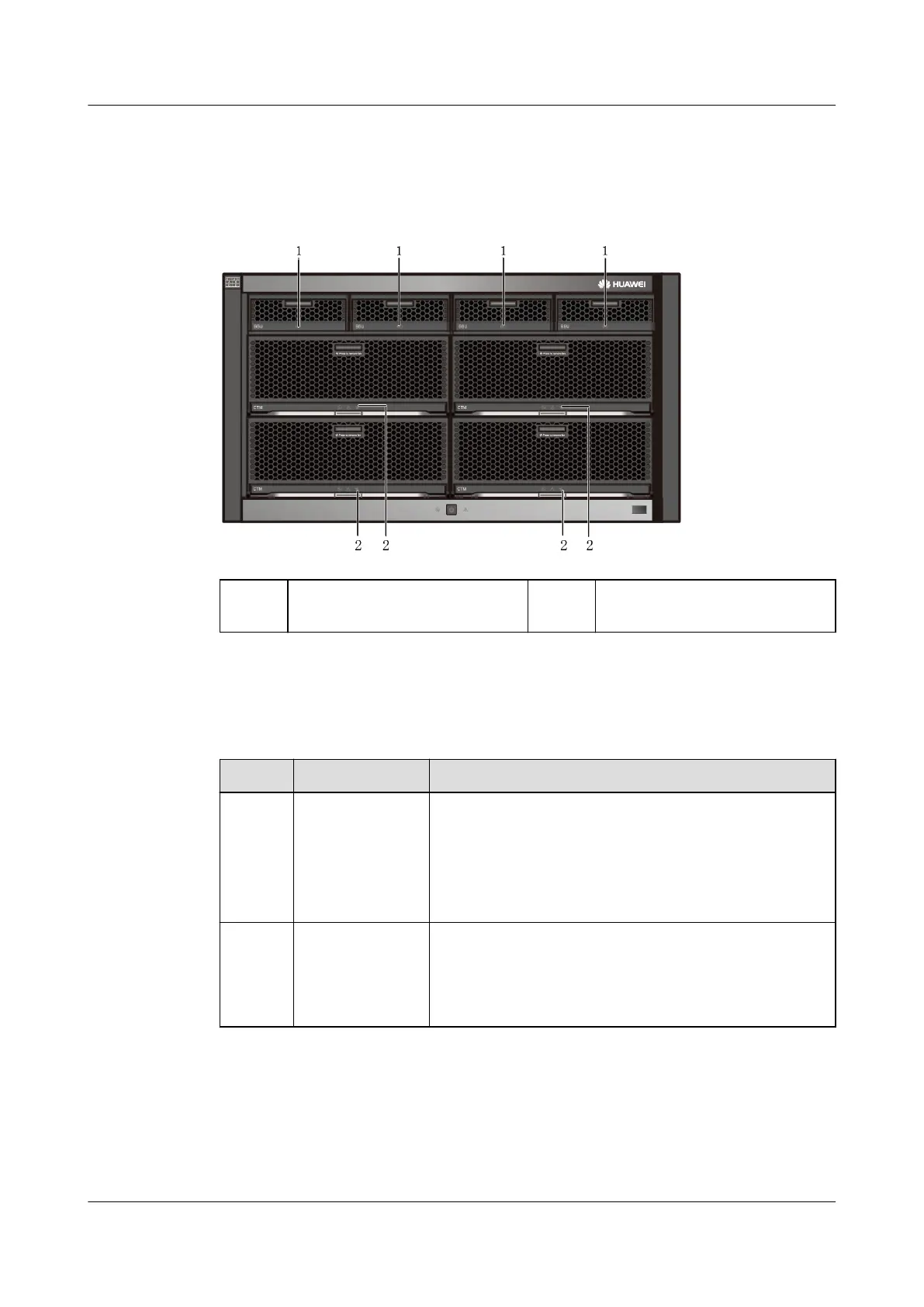
Figure 6-125 shows the indicators on the front panel of a controller enclosure.
Figure 6-125 Indicators on the front panel of a controller enclosure
1 Running/Alarm indicator on a
BBU
2 Running/Alarm indicator on a
fan module
Table 6-5 describes the indicators on the front panel of a controller enclosure.
Table 6-5 Indicators on the front panel of a controller enclosure
No.
Indicator Status and Description
1 Running/Alarm
indicator on a
BBU
● Steady green: The BBU is fully charged.
● Blinking green (1 Hz): The BBU is being charged.
● Blinking green (4 Hz): The BBU is being
discharged.
● Steady red: The BBU is faulty.
2 Running/Alarm
indicator on a
fan module
● Steady green: The fan module is working
properly.
● Steady red: The fan module is faulty.
● O: The fan module is powered o.
Figure 6-126 shows the indicators on the rear panel of a controller enclosure.
OceanStor V5 Series
Parts Replacement 6 Replacing CRUs
Issue 15 (2019-12-30) Copyright © Huawei Technologies Co., Ltd. 131

 Loading...