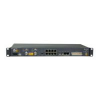
1 Connection status indicator 2 Data transmission status indicator
Figure 2-14 SM251 ports and indicators
1 Connection status indicator 2 Data transmission status indicator
PCIe Slot Layout
Figure 2-15 shows the PCIe slot layout of the RH2288 V3.
Figure 2-15 PCIe slot layout
PCIe Devices
The I/O module provides slots 6 to 8.
The I/O module supports 2-slot PCIe riser module or 3-slot PCIe riser module, but three slots
are always displayed on the panel. For a 2-slot PCIe riser module, slot 8 is unavailable.
Table 2-2 describes the mapping between PCIe devices and CPUs, and the PCIe
specifications of the RH2288 V3.
NOTE
The PCIe devices mapping to a vacant CPU socket are unavailable.
Table 2-2 PCIe device description
PCI
e
Dev
ice
CP
U
PCIe
Stan
dard
Connec
tor
Width
Bus
Width
Port
Nu
mbe
r
Root
Port
(B/D/F
)
Device
(B/D/F)
Slot Size
Slot
4
CP
U 1
PCIe
3.0
x8 x8 Port
3A
00/03/0 04/00/0 Half-height
half-length
RH2288 V3 Server
User Guide
2 Overview
Issue 32 (2019-03-28) Copyright © Huawei Technologies Co., Ltd. 14

 Loading...


