RMS-SNMP01A SNMP Card
User Manual
3 Installation and Basic Settings
Copyright © Huawei Technologies Co., Ltd.
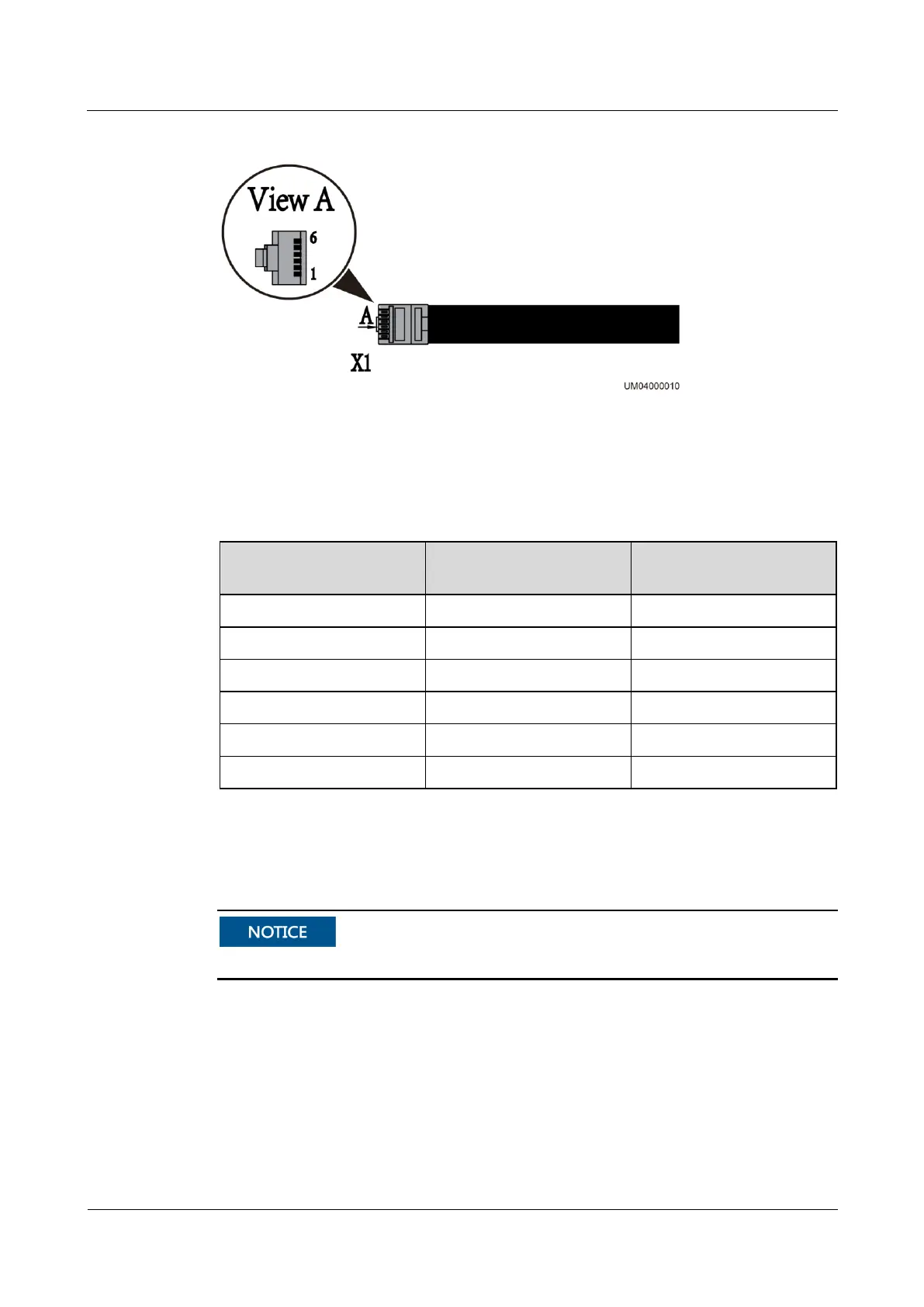
Figure 3-4 RJ11 terminal
Figure 3-4 shows the pin sequence in the RJ11 terminal. In view A, the pins in the RJ11
terminal are numbered 1 to 6 (X1.1 to X1.6) from bottom up. Table 3-2 lists the signals
corresponding to each pin in the RJ11 terminal.
Table 3-2 Mapping between wiring terminals and signals
RJ11 Terminal to the
SNMP Card
ENR1DETA MODULE
RJ11 Terminal Signal
3.5.2 AI/DI Module
AI/DI_1 is a 12 V level output port that cannot connect to an external power source.
AI/DI Module Types
The SNMP card supports only one AI/DI module, and its model is MUE06A. If the SNMP
card is configured with the AI/DI module, it can support one AI/DI signal port. This port
provides 12 V DC outputs for sensors and offers internal overcurrent protection. For details
about other functions and the methods of using these functions, see the ECC500
V600R001C03 User Manual.

 Loading...