RMS-SNMP01A SNMP Card
User Manual
3 Installation and Basic Settings
Copyright © Huawei Technologies Co., Ltd.
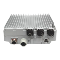
Set the address of the AI/DI module to 3 (toggle switches 1 to 3 are used to set the address of the
AI/DI module, and toggle switch 4 is used to enable or disable the resistance for the RS485
interface). Toggle switches 1 and 2 are set to ON and toggle switch 3 is set to OFF, as shown in
Figure 3-5.
COM_IN port is for communication. The baud rate is 9600.
If both the CIM and independent AI/DI module are deployed, use the COM_OUT port to cascade
with the CIM.
Electrical level is output from the AI/DI_1 port. Pin 3 of the AI/DI_1 port is DC 12 V, 54 mA, and
pin 8 of the AI/DI_1 port is GND, as shown in Figure 3-5.
When the signal is unstable due to signal reflection which is caused by the long communication
route (greater than 200 m), set toggle switch 4 to ON for the farthest AI/DI module, as shown in
Figure 3-5. After the DIP switch settings are modified, power off and restart the AI/DI module for
the new settings to take effect.
The AI/DI_1 port can connect to the UPS run indicator. Table 3-3 shows the indicator status.
Figure 3-5 AI/DI module
(1) Port for the SNMP card
(2) Port for DC 12 V power
(3) DC 15 V power input
(adapter required)
Table 3-3 Status of UPS run indicator connected to the AI/DI_1 port
Single
UPS/Parallel
System
AI/DI_1 Port
Output Voltage
Bypass mode or no
power supply mode
Normal mode,
battery mode, mains
ECO mode, or
battery ECO mode
All UPSs work in
normal mode,
battery mode, mains
ECO mode, or

 Loading...