RMS-SNMP01A SNMP Card
User Manual
3 Installation and Basic Settings
Copyright © Huawei Technologies Co., Ltd.
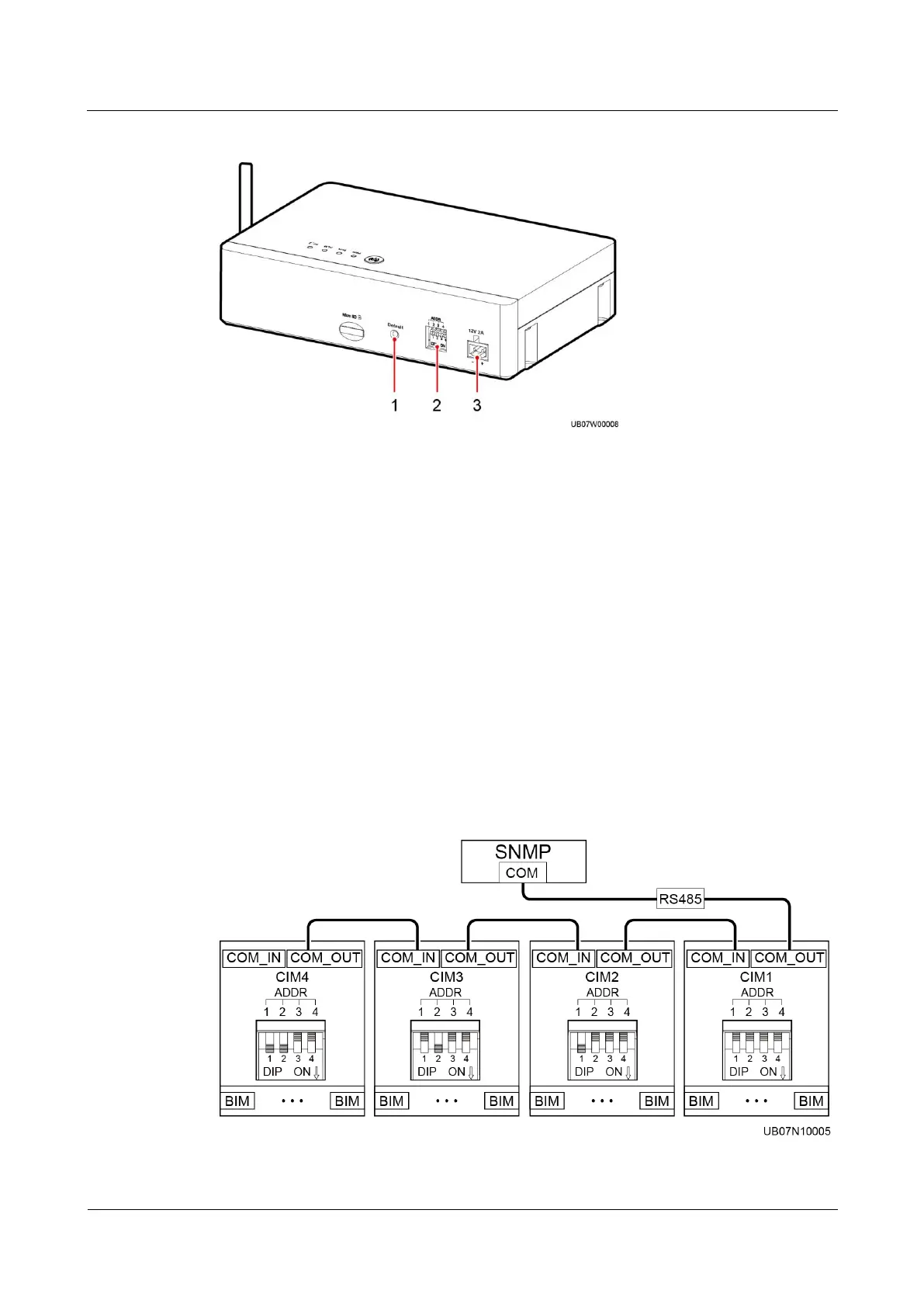
Figure 3-9 CIM rear
(2) RS485 communications
address DIP switch
The COM_OUT ports on the CIMs connect to the COM port on the SNMP card, as shown in
Figure 3-10. The CIMs collect battery status data from the downstream BIM groups through
wireless communication and send information to the SNMP card. If both the CIMs and
independent AI/DI module are deployed, cascade the CIMs with the independent AI/DI
module, as shown in Figure 3-11.
When the SNMP card connects to the CIMs, the DIP switches of the CIMs need to be set. The
DIP switch of the first CIM must be set to the start address (0000), and the DIP switches of
the CIMs must be consecutive. If the number of CIMs is 4, then the DIP switch of CIM1
(from high to low, DIP4 to DIP1) is 0000, CIM2 0001, CIM3 0010, and CIM4 0011. For
details about the networking between the CIMs and BIMs, see the user manual delivered with
the iBAT 2.0.
Figure 3-10 CIM communications cable connecting to the SNMP card

 Loading...