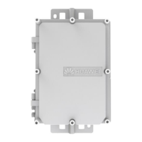
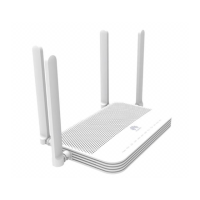
Figure 5-31 Connecting an Ethernet cable
Step 3 Lay out the Ethernet cable along a cabinet and route the cable through the cable
hole for the signal cables at the top (overhead cabling) or bottom (underoor
cabling) of the cabinet.
Step 4 Remove the temporary labels and attach labels (2 cm away from the connectors)
at both ends of the Ethernet cable.
----End
Follow-up Procedure
Verify the following after the installation:
● The labels at both ends of the cable are correct, clear, neat, and facing the
same direction.
● The cables and connectors are free of any damage or breakage and are
connected properly and reliably.
5.4.6 Installing Optical Transceivers and Connecting Optical
Fibers
This section describes how to install optical transceivers on the GE , 10GE, or 40GE
optical ports of the USG and connect them to the ports of the peer device using
optical
bers according to the network plan.
Context
The USG supports both 1 Gbit/s , 10 Gbit/s, and 40 Gbit/s optical modules. The
optical modules at both ends are the same, including the optical ber type
(single-mode or multi-mode), optical
ber connector type (LC/PC, SC/PC, FC/PC,
or MPO/PC-MPO/PC), and transmission rate. If dierent optical modules are used
at the two ends, the communication may fail.
HUAWEI USG6000E Series
Hardware Guide 5 Hardware Installation
Issue 08 (2022-04-20) Copyright © Huawei Technologies Co., Ltd. 552
 Loading...


