O.18 Part. N. 8000 H0368 (09-2008)
“KIT” ASSEMBLING INSTRUCTIONS
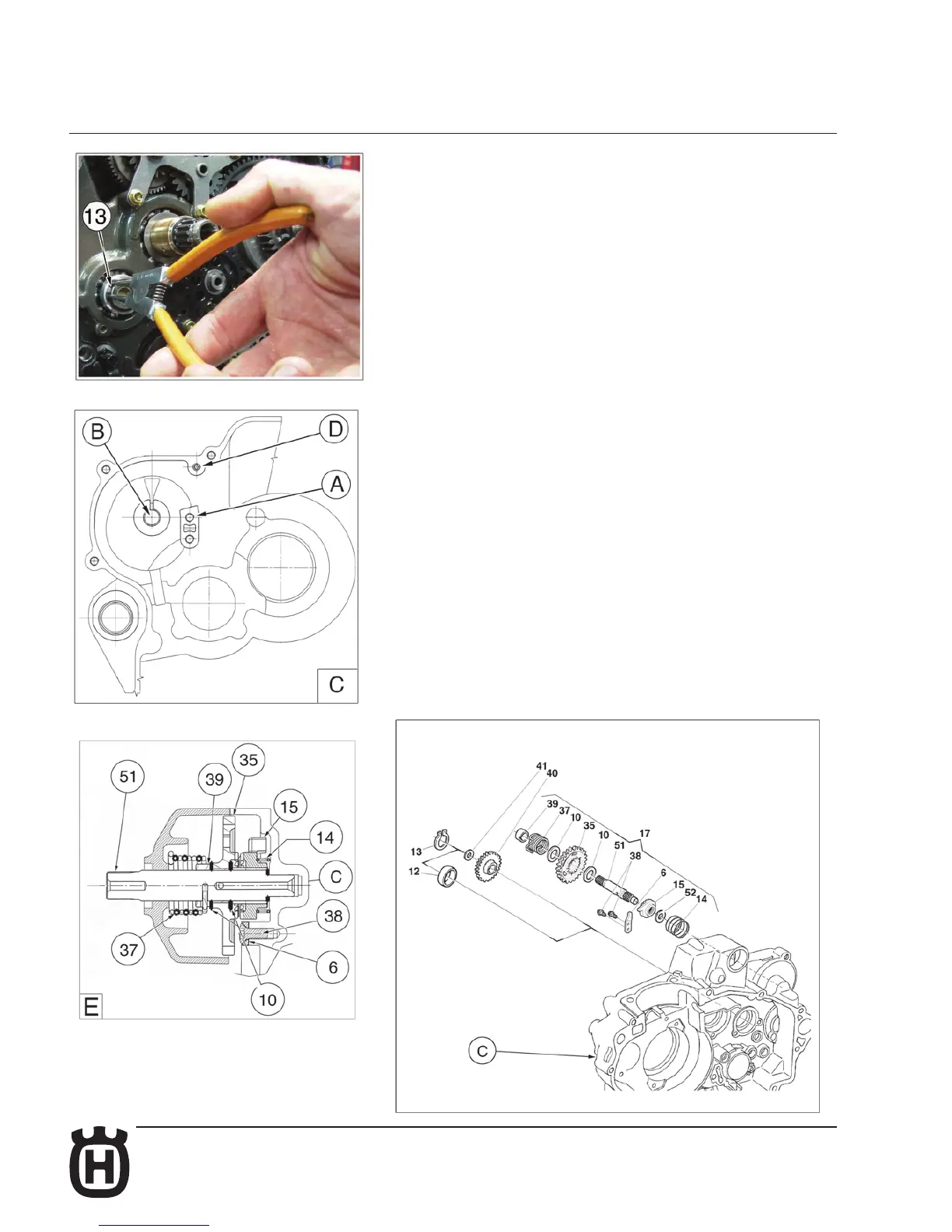
Remove the circlip (13), the spacer (12) then fasten the plate (6) in the holes (A)
on the R.H. crankcase (C) using the two screws (38) M6x14 (+LOCTITE 243).
Assemble the shaft assy. (E) in the seat (B) then place the hook return spring
(37) in the crankcase hole (D).
Assemble idling gear (40), washer (41) and circlip (13).