Notes:
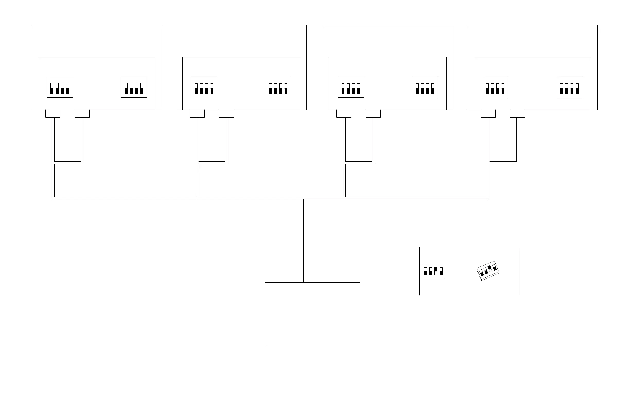
1. Serial terminator DIP switches (S1) and Serial ID DIP switches (S2) are not used for
discrete-only CNC connections.
2. The CNC must provide separate inputs and outputs for each XPR plasma power
supply. Sole exceptions are PLASMA START+/- and HOLD+/-. These can be wired
in parallel from one set of CNC outputs to all XPR plasma power supplies.
Discrete cable Discrete cable
CNC interface
Unit 2
Plasma power supply
Unit 1
Plasma power supply
Unit 3
Plasma power supply
Unit 4
Plasma power supply
Discrete cable
141322
Control board
Serial terminator DIP switch
Serial ID DIP switch
Serial terminator DIP switch
Serial ID DIP switch
Serial terminator DIP switch
Serial ID DIP switch
Serial terminator DIP switch
Serial ID DIP switch
141322
Control board
141322
Control board
141322
Control board
013403
Switch 3 is in the ON position.
Switches 1, 2, and 4 are in the OFF position.
Discrete cable Discrete cable Discrete cable Discrete cable
DIP switch setting example

 Loading...


