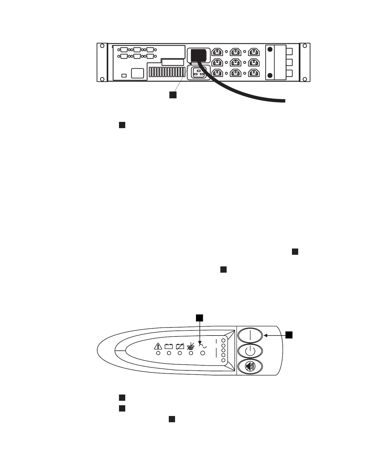
1
Main power cable
If possible, ensure that the two UPSs are not both connected to the same
power source. Ensure that you comply with the following requirements for
the 2145 UPS:
v Each 2145 UPS should be connected to a separate branch circuit.
v A UL-listed 15 A circuit breaker must be installed in each branch circuit that
supplies power to the 2145 UPS.
v The voltage that is supplied to the 2145 UPS must be 200 – 240 V single
phase.
v The frequency that is supplied must be 50 or 60 Hz.
Note: If the 2145 UPS is cascaded from another UPS, the source UPS must
have at least 3 times the capacity per phase and the total harmonic
distortion must be less than 5%. The UPS should also have input
voltage capture that has a slew rate of no more than 3 Hz per second.
10. All front panel indicators of the 2145 UPS flash for a short time while the 2145
UPS runs a self-test. When the test is complete, the mode indicator
1
flashes
to show that the 2145 UPS is in standby mode; see Figure 90.
Press and hold the 2145 UPS On button,
2
in Figure 90, until you hear the
2145 UPS beep (approximately one second). The mode indicator stops flashing
and the load-level indicators display the percentage of load that is being
supplied by the 2145 UPS. The 2145 UPS is now in normal mode and is
charging its battery.
1
Mode indicator
2
On button
If the mode indicator
1
is flashing red and the alarm is sounding, the
voltage range setting might not be correct. When a SAN Volume Controller
2145-4F2 is connected to the 2145 UPS, the SAN Volume Controller 2145-4F2
1
Figure 89. Installing the 2145 UPS power cable
+- +-
25%
100%
2
11
Figure 90. Power switch and indicators on the 2145 UPS
128 IBM System Storage SAN Volume Controller: Hardware Installation Guide

 Loading...


