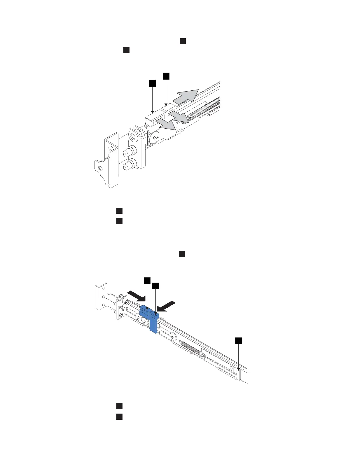
3. Gently push the latch lock
2
away from the rail as you move the latch
lever
1
toward the far end of the rail (Figure 92). The latch-lock carrier
assembly slides against the spring tension.
1
Latch-lever
2
Latch-lock
4. Continue to slide the latch-lock carrier for approximately 13 mm (0.5 in). The
latch-lever engages a hole in the back bracket assembly and holds the
latch-lock carrier in the retracted position.
5. Push the back rail bracket
1
(Figure 93) toward the front of the rail until it
stops. The rail is now at its shortest adjustment.
1
Back rail bracket
2
Latch-lock
1
2
1
2
23nl1c
Figure 92. Opening the front latch-lock carrier assembly
2
1
3
Figure 93. Opening the back latch-lock carrier assembly
130 IBM System Storage SAN Volume Controller: Hardware Installation Guide

 Loading...


