3
Latch-lever
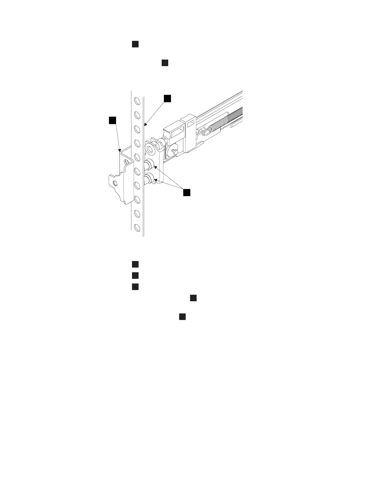
6. Place the front end of the left rail in the rack cabinet. Align the top of the
front bracket
1
(Figure 94) with the required EIA marking that is on the
rack.
1
Front bracket
2
Rack-mounting flange
3
Locating pins
7. Align the locating pins
3
with the holes that are in the rack-mounting
flange.
8. Push the latch lock
2
(Figure 95 on page 132) away from the rail to release
the carrier. The latch-lock carrier slides toward the front of the rack and the
locating pins project through the holes that are in the front flange and in the
front rail bracket.
Important: Ensure that the locating pins are fully extended through the front
rail bracket.
1
2
3
Figure 94. Installing the front end of the rail
Appendix B. SAN Volume Controller 2145-4F2 131

 Loading...


