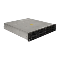
In Figure 55, the Fibre Channel switches are not connected together through an
ISL. Each switch forms its own SAN fabric. This configuration is also the
configuration to use for a dual-node cluster configuration.
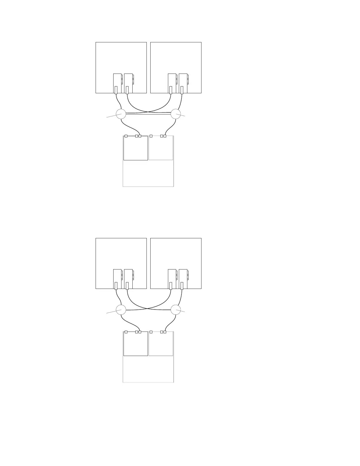
In Figure 56 on page 59, the Fibre Channel switches are not connected together.
Each switch forms its own SAN fabric.
Host system
with two host
adapters
Host system
with two host
adapters
Fibre
Channel
switch
Fibre
Channel
switch
Inter-Switch Link
DS3500
Figure 54. Example of a single Fibre Channel SAN fabric configuration
Host system
with two host
adapters
Host system
with two host
adapters
Fibre
Channel
switch
Fibre
Channel
switch
DS3500
Figure 55. Example of a dual Fibre Channel SAN fabric configuration
58 System Storage DS3500 and EXP3500: Installation, User’s, and Maintenance Guide

 Loading...