2
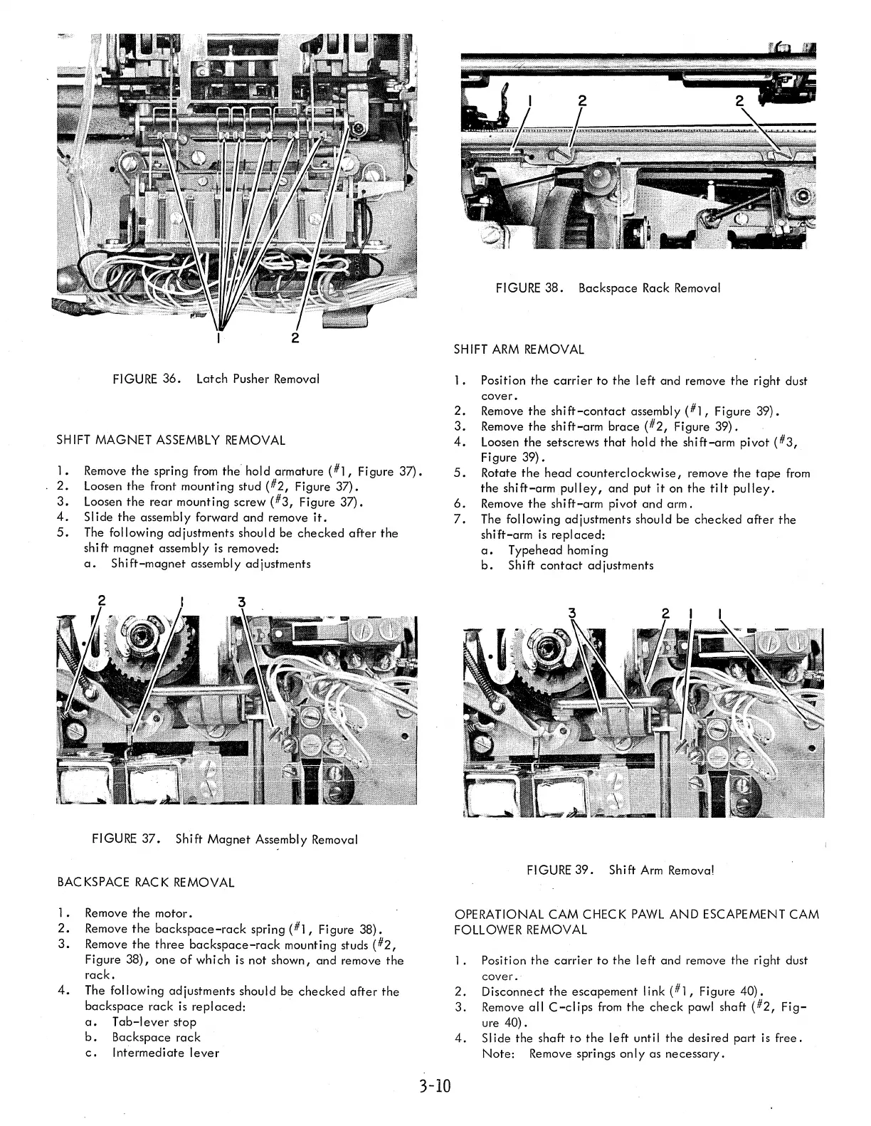
FIGURE
36.
Latch Pusher Removal
SH
1FT
MAGNET
ASSEMBLY
REMOVAL
].
Remove
the
spring from the' hold armature
(#],
Figure
37).
2.
Loosen
the
front mounting stud
(#2,
Figure
37).
3.
Loosen
the
rear
mounting
screw
(#3,
Figure
37).
4.
Slide
the
assembly forward
and
remove
it.
5.
The following adjustments should be
checked
after
the
shi ft magnet assembly is removed:
a.
Shift-magnet
assembly adjustments
FIGURE
37.
Shift
Magnet
Ass~mbly
Removal
BACKSPACE
RACK
REMOVAL
].
Remove
the
motor.
2.
Remove
the
backspace-rack
spring
(#],
Figure
38).
3.
Remove
the
three
backspace-rack
mounting studs
(#2,
Figure
38),
one
of
which is not shown, and remove
the
rack.
4.
The following adjustments should be
checked
after
the
backspace
rack
is
replaced:
a.
Tab-I
ever
stop
b.
Backspace
rack
c.
Intermediate
lever
3-10
FIGURE
38.
Backspace Rack Removal
SHIFT
ARM
REMOVAL
].
Position
the
carrier
to
the
left
and remove
the
right dust
cover.
2.
Remove
the
shift-contact
assembly
(#],
Figure
39).
3.
Remove
the
shift-arm
brace
(#2,
Figure
39).
4.
Loosen
the
setscrews
that
hold
the
shift-arm
pivot
(#3,
Figure
39).
5.
Rotate
the
head
counterclockwise,
remove
the
tape
from
the
shift-arm
pulley,
and
put
it
on
the
tilt
pulley.
6.
Remove
the
shift-arm
pivot
and
arm.
7.
The following adjustments should be
checked
after
the
shift-arm
is
replaced:
a.
Typehead homing
b.
Shift
contact
adjustments
FIGURE
39.
Shift
Arm
Remova!
OPERATIONAL CAM CHECK
PAWL
AND
ESCAPEMENT CAM
FOLLOWER REMOVAL
].
Position
the
carrier
to
the
left
and
remove
the
right dust
cover.
2.
Disconnect
the
escapement
link
(#],
Figure
40).
3.
Remove
all
C-clips
from
the
check
pawl shaft
(#2,
Fig-
ure
40).
4.
Slide
the shaft
to
the
left
until
the
desired part is
free.
Note:
Remove springs
only
as
necessary.