Section
2.
Adjustments
ADJUSTMENT
THEORY
This
adjustment
is
extremely important because
the
rollers
on the latch bai I
MUST
contact
their
respective
selector
MOTOR AND
DRIVE
cams
at
the
same point and with
the
same pressure in
ord.
er
to insure
tha"t
both cams
operate
the
bail
together.
1.
Drive Belt - Adjust
the
motor mounting brackets forward
or
back
to obtain a minimum amount
of
belt
noise.
Both
ends of the motor must be adjusted
the
same in order
to
maintain
the
rotor shaft
perpendicular
to
the
drive belt.
The
belt
must never be so loose
that
jumping cogs
on
the
motor pulley
is
a possibility.
Check
by operating
the
shift mechanism while holding
the
carrier
with
the
car-
rier return
in
operation.
This
loads
the
motor
to
a point
where failure
will be most
probable.
2.
Motor Pulley - Adjust the motor
pulley
left or right so
that
the
drive
belt
rides fully on
the
teeth
of
both
pul-
leys without rubbing
the
flange of
either.
Position
the
retaining
clip
for
.005"
to
.015"
end
play.
3.
Motor Clutch Pawl Stops
(Fig.
1)
-
Form
for a
clearance
of
.010"
to
.020"
between
the
clutch
pawl
tip
and
pul-
ley
ratchet
when
the
pulley
is
manually
rotated.
Form
This Tip
FIGURE
1.
Motor
Clutch
Pawls
4.
Idler Gears - Adjust
the
idler
gear
studs so
that
minimum
backlash
is
present between mating
gears.
The
mechan-
ism
must be free
of
binds throughout 360
0
rotation of
the
gears.
Minimum backlash
is
necessary to prevent
erratic
opera-
tion
of
the
drive train
and
to insure minimum overthrow
of
the
driven
shafts.
The
lower
idler
gear
must be adjusted first because
the
upper
idler
gear
is
adjusted
to
the
final position
of
the
lower
gear.
CAUTION: After
any
removal and replacement
of
the
left hand
cycle
shaft
bearing,
the
mesh of
the
lower
id-
ler
gear
must be
checked.
The lower idler
gear
stud
is
mounted
to
the
bearing
plate;
therefore
any
slight
rota-
tion of
the
plate
wi
11
affect
the
gear
mesh.
Selection
Mechanism
5.
latch
Bail Shaft - Adjust
the
plate
that
supports
the
right
end
of
the
bail shaft so
that
the
bail shaft is
parallel
to
the
cycle
shaft.
2-1
The
bail shaft
is
set
at
the
factory and should not require
a readjustment
un
less
the
plate
becomes loosened
or
parts replacement
is
necessary.
This
is
a
difficult
ad-
justment to make
and
should not be loosened unless
ab-
solutely necessary.
The bail shaft
plate
must be adjusted both
vertically
and
horizonta lIy in order to make
the
rollers
of
the
latch
bai I
ride
their
respective cams
equally.
Changing
either
the
vertical
or horizontal position will
affect
the
other;
therefore both adjustments must be considered
together
and adjusted
alternately
until both
are
correct.
If
a
re-
adjustment
is
necessary,
the
following procedure may
be
used.
a.
The
correct
vertical
position
is
obtained
by raising
or lowering
the
bail shaft mounting
plate
until both
bail
rollers have
equal
pressure
against
their
re-
spective
cams.
Check
by testing
the
drag on strips
of
paper inserted between
the
rollers and
the
cams.
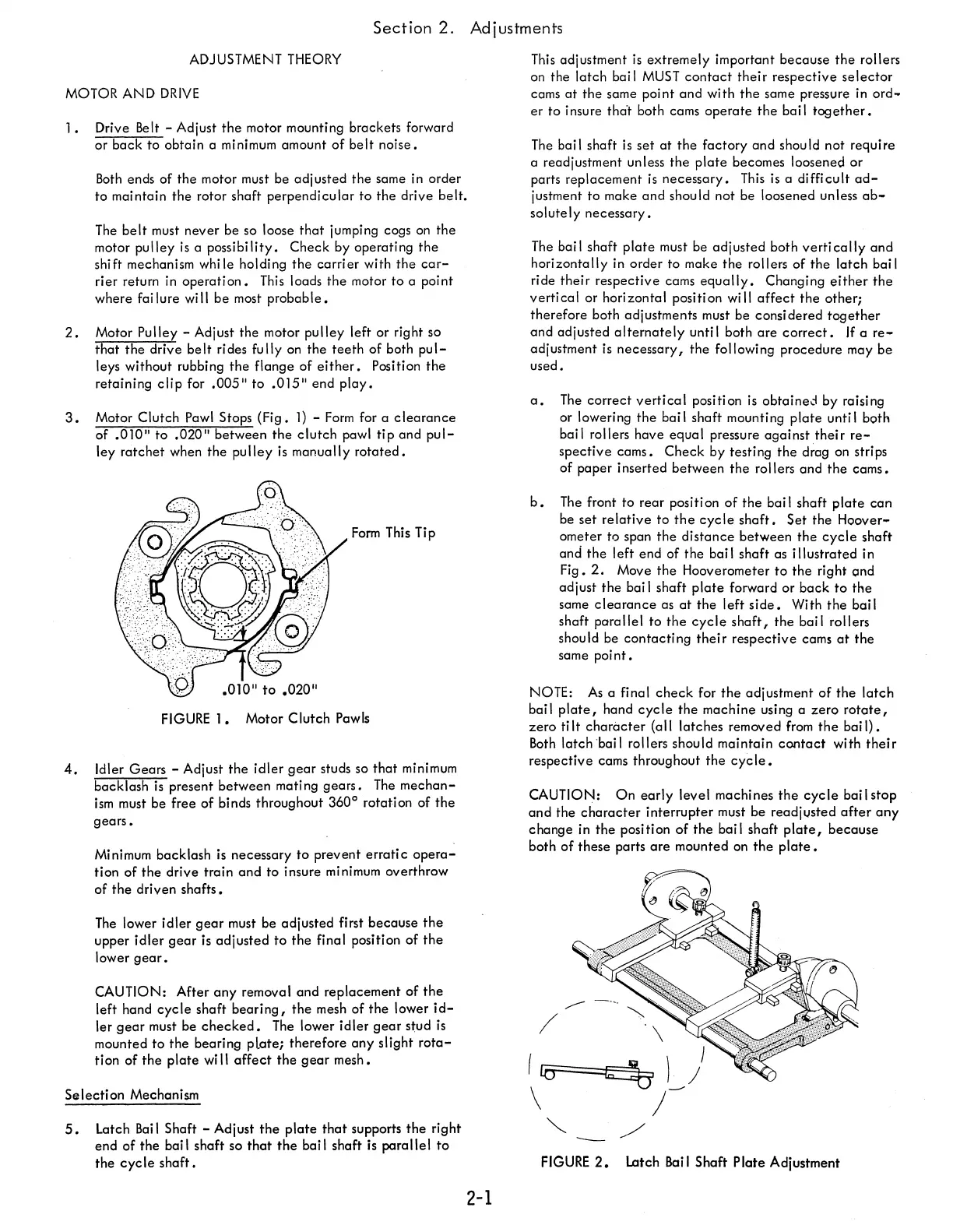
b.
The
front to rear positi on
of
the
bail shaft
plate
can
be
set
relative
to
the
cycle
shaft.
Set
the
Hoover-
ometer to span
the
distance
between
the
cycle
shaft
and
the
left end
of
the
bail shaft as
illustrated
in
Fig.
2.
Move
the
Hooverometer
to
the
right
(;md
adjust
the
bai I shaft
plate
forward or
back
to
the
same
clearance
as
at
the
left
side.
With
the
bai I
shaft
parallel
to
the
cycle
shaft,
the
bai I rollers
should be
contacting
their
respective cams
at
the
same
point.
NOTE:
As
a final
check
for
the
adjustment
of
the
latch
bail
plate,
hand
cycle
the
machine using a
zero
rotate,
zero
ti
It
character
(a
II
latches
removed
from
the
bai
I)
•
Both
latch 'bai I rollers should maintain
contact
with
their
respective cams throughout
the
cyc
Ie.
CAUTION:
On
early
level machines
the
cycle
bai I stop
and
the
character
interrupter
must be readjusted
after
any
change in
the
position
of
the
bail shaft
plate,
because
both
of
these parts
are
mounted on
the
plate.
,--
"'"
/
\
leo
q
t_J
J
\
)
"---
.-/
FIGURE
2.
Latch
Bai
I Shaft
Plate
Adjustment