11. Tab Interlock
Contact-
a.
Form
(in
circled
area)
the
actuating
wire (left or
right) so
that
it
contacts
the
actuating
arm
near
the
right
angle
bend
(Fig.
174).
b.
With
the tab
interposer
released
and
the
Tab/Sp/BS
cam on its high
point,
position
the
mounting
brack-
et
(front
to
rear) so
that
the
actuating
arm overlaps
(.040" minimum) the
actuating
wire
(Fig.
174).
This insures
that
the
actuating
wire does not
get
a-
bove
the
actuating
arm.
Actuating
Arm
(Tab Torque Bar)
Overlaps
.040"
Min.
Contact
Actuating
Arm
Contacts
Actuating
Wire
In
The
Area
Circled
Actuating
Wire
(Form
In
This Area)
Mtg.
Bracket
(Front to Rear
Adj.)
FIGURE
174.
Interlock
Contact
(Early)
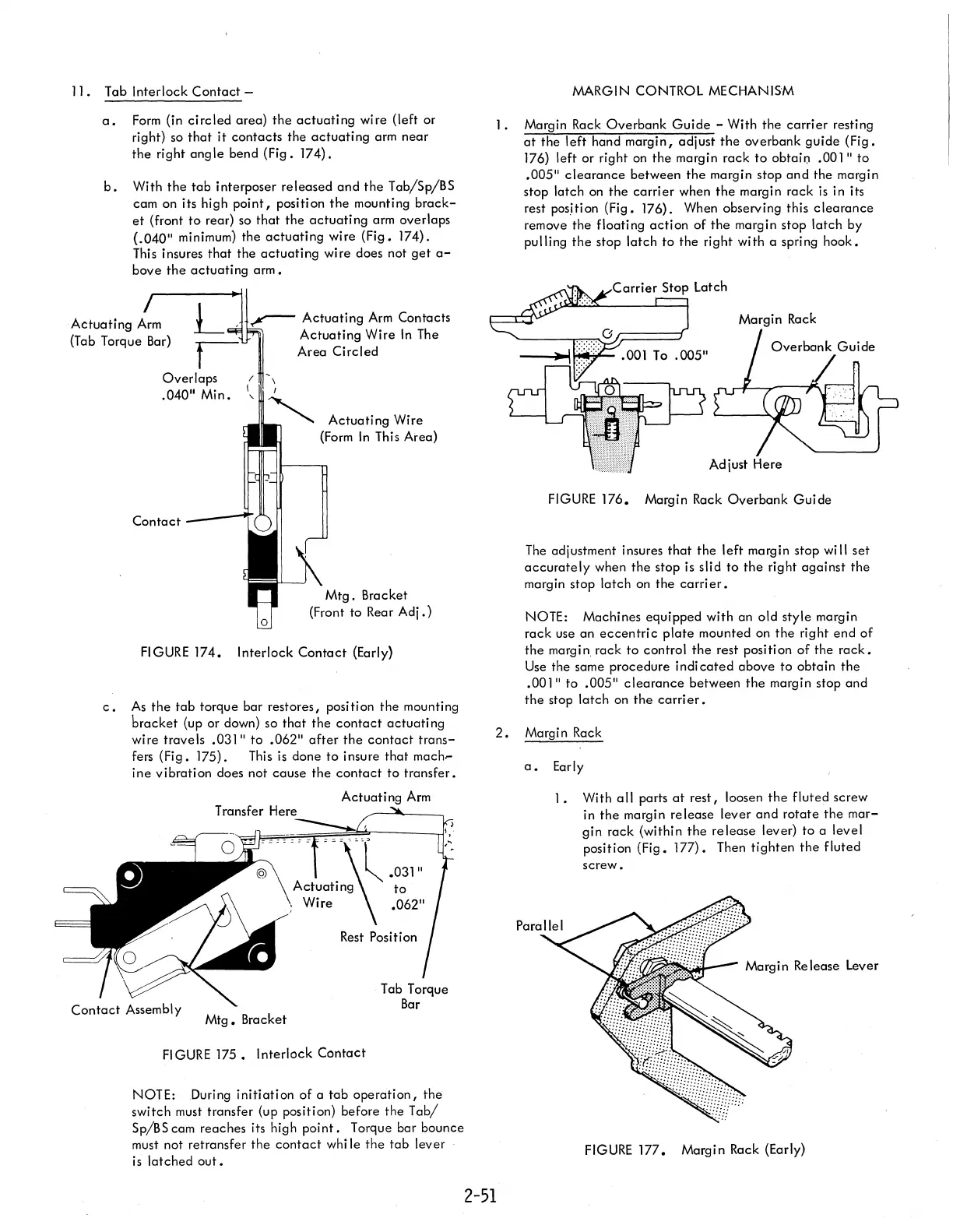
c.
As
the tab
torque bar restores, position
the
mounting
bracket
(up or down) so
that
the
contact
actuating
wire travels .031"
to
.062"
after
the
contact
trans-
fers
(Fig.
175). This
is
done
to
insure
that
mach-
ine
vibration
does not
cause
the
contact
to
transfer.
Actuating
Arm
==~'OOl.031"
Actuating
to
Wire
.062"
Rest
Position
Mtg.
Bracket
FIGURE
175.
Interlock
Contact
NOTE: During
initiation
of
a
tab
operation,
the
switch must transfer (up position) before the
Tab/
Sp/BS cam reaches its high
point.
Torque bar bounce
must not retransfer
the
contact
whi
Ie
the tab
lever
is
latched
out.
MARGIN CONTROL MECHANISM
1.
Margin Rack
Overbank
Guide
- With
the
carrier
resting
at
the
left
hand
margin,
adjust
the
overbank
guide
(Fig.
176)
left or right on
the
margin
rack
to
obtai!) .00
I"
to
.005"
clearance
between
the
margin stop
and
the margin
stop
latch on
the
carrier
when
the
margin rack is in its
rest pos.ition (Fig.
176). When observing this
clearance
remove the floating
action
of
the
margin stop
latch
by
pulling
the
stop
latch
to the right with a spring
hook.
FIGURE
176.
Margin Rack
Overbank
Guide
The
adjustment insures
that
the
left
margin stop will
set
accurately
when
the
stop is slid
to
the
right
against
the
margin stop latch on the
carrier.
NOTE: Machines equipped with an old style margin
rack
use an
eccentric
plate
mounted on
the
right
end
of
the
margin. rack
to
control
the
rest position
of
the
rack.
Use
the same procedure
indicated
above
to
obtain
the
.001"
to
.005"
clearance
between
the
margin stop and
the
stop latch on
the
carri
er.
2.
Margin Rack
2-51
a.
Early
1.
With
all
parts
at
rest,
loosen
the
fluted screw
in
the
margin
release
lever
and
rotate
the
mar-
gin
rack (within
the
release
lever) to a level
position
(Fig.
177).
Then
tighten
the
fluted
screw.
FIGURE
177.
Margin Rack (Early)