(b) Degree Wheel Method - With
the
machine
at
zero
degrees (cycle
clutch
latched
at
rest)
se-
lect
a
-5
rotate,
0
tilt
character
and
hand
cy-
cle
the machine slowly. The
cycle
clutch
spring should slip and stop driving
at
170 to
175
degrees.
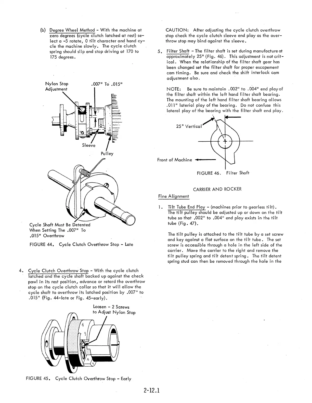
Nylon
Stop
Adjustment
Cycle
Shaft
Must
Be
Detented
When Setting The
.007"
To
.015"
Overthrow
.007"
To'
.015"
Pulley
FIGURE
44.
Cycle
Clutch Overthrow Stop - Late
4.
Cycle
Clutch
Overthrow Stop - With
the
cycle
clutch
latched
and
the
cycle
shaft
backed
up
against
the
check
pawl in its rest
position,
advance
or retard
the
overthrow
stop on
the
cycle
clutch
collar
so
that
it
will
allow
the
cycle
shaft
to overthrow its
latched
position by
.007"
to
;015"
(Fig.
44-late
or Fig.
45-early).
FIGURE
45.
Cycle
Clutch Overthrow Stop - Early
CAUTION:
After
adjusting
the
cycle
clutch
overthrow
stop
check
the
cycle
clutch
sleeve
end
playas
the
over-
throw stop may bind
against
the
sleeve.
5.
Fi
Iter Shaft - The
filter
shaft is
set
during manufacture
at
approximately
25°
(Fig.
46).
This adjustment
is
not
crit-
ical.
When the relationship
~f
the
filter
shaft
gear
has
been
changed
set
the
filter
shaft for proper
escapement
cam
timing.
Be
sure and
check
the shift
interlock
cam
adjustment a
Iso.
NOTE:
Be
sure to maintain
.002"
to
.004"
end
playof
the filter shaft within the left hand
filter
shaft
bearing.
The mounting
of
the
left
hand
filter
shaft
bearing
allows
.011"
laterial
play
of
the
bearing.
Do
not confuse this
lateral
play
of
the
bearing with
the
filter
shaft
end
play.
25°
Vertical/\
Front
of
Machine
....
_--
FIGURE
46.
Filter Shaft
CARRIER
AND
ROCKER
Fine Alignment
1.
Ti
It
Tube
End
Play - (machines prior
to
gearless ti
It).
The
tilt
pulley
should be adjusted up or down on
the
tilt
tube so
that
.002"
to
.004"
end
play
exists in
the
tilt
tube (Fig.
47).
The
tilt
pulley
is
attached
to
the
tilt
tube
by a set screw
and key
against
a flat surface on the ti
It
tube.
The set
screw
is
accessible
through a hole in
the
left side
of
the
carrier.
Move
the
carrier
to
the
right
and
remove the
tilt
pulley
spring and
tilt
detent
spring.
The
tilt
detent
spring stud
can
then
be
removed through
the
hole in
the
2-12.1