The .025"
to
.035" skirt
clearance
allows
the
rotate
de-
tent
to
enter
and withdraw
from
the
type head notch
area
at
the
proper time with respect to
the
rotating
typehead.
If
this
clearance
is
too small
the
rotate
detent
will
enter
the
notch
area
too
early
and
withdraw too
late.
This
will also cause an intermittent erroneous
character
to
print,
parts
breakage,
or unwanted roller
droppage.
Too
much skirt
clearance
will
only
cause premature wear on
the
detent
mechanism due to
the
leverage
gain.
Since
the
detent
cam
and
print cam
are
both keyed
to
the
print
shaft,
the
relationship between
the
detent
tim-
ing
and
the point
at
whi ch
the
typehead
prints
is
non-
adjustable.
The design
of
the
two cams
is
such
that
the
detents will be fully
seated
in
their
notches when
the
typehead
contacts
the
platen
durin~
a print
operation.
The
only
thing
that
can
affect
this timing relationship
is
the
position
of
the
detent
cam follower mounting
brack-
et.
The position
of
this
bracket
is
fixed
at
the factory
and shou
Id
not be
changed.
II.
Detent Mechanism (Gearless
Ti
It)
The
detent
mechanism must be adjusted
to
satisfy
the
following conditions:
a.
With
the
cycle
shaft
at
rest and
the
typehead
man-
ually
held in a
tilt
two position, adjust the ribbon
feed and
detent
cam left
or
right
on
the print
sleeve
(Fig.
57)
so
that
the
rotate
detent
wi
II c
lear
the
detent
teeth
on
the
type head skirt
by
.025" to .035"
(Fig.
58).
Feed Cam Follower
FIGURE
57. Detent Cam Adjustment
.025"
To
FIGURE
58.
Skirt
Clearance
2-16
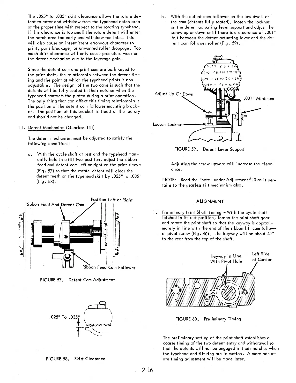
b.
With
the
detent
cam follower
on
the
low dwell of
the cam (detents fully
seated),
loosen the locknut
on
the
detent
actua ting
lever
support and adjust
the
screw up
or
down unti I
there
is
a
clearance
of
.001"
felt between
the
detent
actuating
lever and the
de-
tent
cam follower roller
(Fig.
59).
.001" Minimum
Loosen Locknut
----:~~~=::::~I
FIGURE
59.
Detent
Lever Support
Adjusting
the
screw upward will increase
the
clear-
ance.
NOTE: Read the
"note"
under Adjustment #10 as
it
per-
tains to
the
gearless ti It mechanism a Iso.
ALIGNMENT
I.
Preliminary Print Shaft Timing - With
the
cycle
shaft
latched in its rest position, loosen
the
print shaft
gear
and rotate
the
print shaft so
that
the
keyway
is
approxi-
mately in line with
the
end of
the
ribbon lift cam
follow-
er
pivot screw (Fig. 60).
The
keyway
wi
II
be about 45°
to
the
rear
from
the
top
of
the
shaft.
FIGURE
60. Preliminary Timing
Left Side
of
Carrier
The preliminary setting of
the
print shaft establishes a
coarse timing
of
the
two
detent
entry
and
withdrawal so
that
the
detents will not be
engaged
in tlleir notches when
the
typehead
and
tilt
ring
are
in motion. A more
accur-
ate
timing adjustment
wi
II be made
later.