2.
Ti
It
Selector
Latches -
Form
the
two stop lugs (Fig. 6
J)
above
the ti
It
selector latches so that
the
latches
wi
II
reset simu Itaneously (under
the
latch bail) just as the
cycle
clutch
check
pawl drops into
the
notch
on
the
check
ratchet
at
the rest position (Fig.
62).
Form
These
Lugs
Up
or
Down
FIGURE
61.
Selector
latch
Stop lugs
Cycle
Shaft
Cycle
Clutch
Check Ratchet
FIGURE
62.
Latches Reset as
Check
Pawl Drops
In
just Link
Up
Or
Down
The
adjustment can
easily
be
checked
by hand cycling a
zero-tilt
character
twice
in succession.
As
the
cycle
shaft begins
to
pass its rest position,
place
your finger
lightly against
the
cycle
clutch
check
pawl while
ob-
serving the
selector
latches.
If
the
adjustment
is
correct
you should feel the
check
pawl drop into the rest position
notch
on
the
check
ratchet
simultaneously as
the
two
se-
lector latches reset under
the
latch
bai
I.
Form
the stop lugs by tapping them up or down with a
hammer and screwdriver.
The
stop lugs shou
Id
be
over-
formed slightly then brought
back
to
the
correct
positio;
otherwise the "memory"
of
the metal will cause them
to
restore toward
their
original position.
NOTE:
It
is
very
important for
each
selector
latch
to
receive
the same amount
of
motion
from
the
latch
bail,
when
operated,.
in order
to
produce
the
proper amount of
motion to
the
tilt
arm link for a desired
selection.
If
one of the stop lugs
is
adjusted too low, its respective
latch
wi
II
reset
early
under
the
latch
bai I producing
an
excessive amount
of
latch
clearance
for
that
latch.
This
means
that
this latch when operated will not
receive
as
much motion
from
the
latch
bail as
the
other latch
wi
II
when
it
is
operated.
This
condition which
is
undesirable
causes the band width
of
the
system
to
increase.
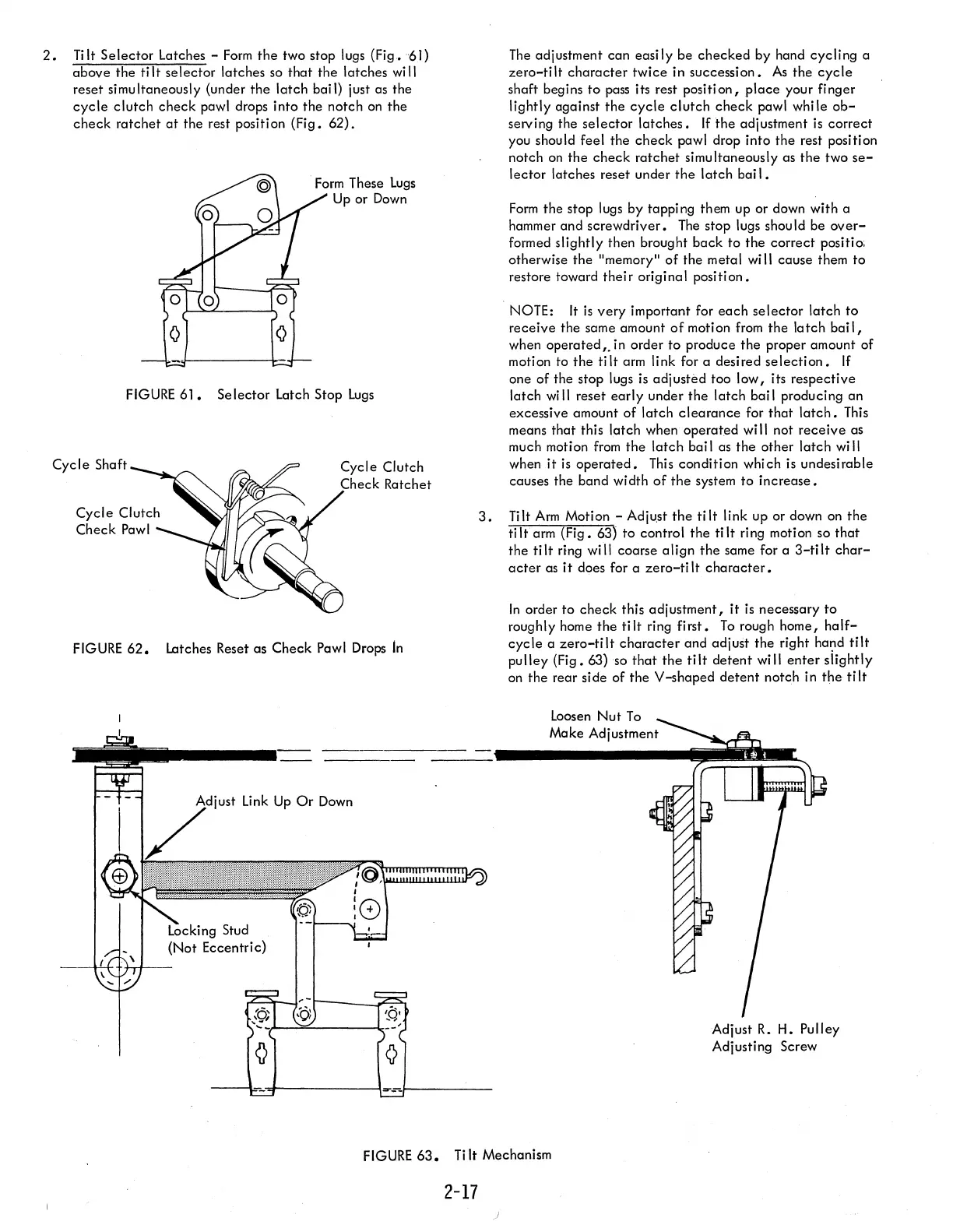
3.
Tilt
Arm
Motion - Adju,st
the
ti
It
link up or down on
the
ti
It
arm (Fig. 63)
to
control
the
tilt
ring motion so
that
the
tilt
ring will coarse
align
the
same for a
3-tilt
char-
acter
as
it
does for a
zero-ti
It
character.
In
order
to
check
this adjustment, it
is
necessary
to
roughly home
the
tilt
ring
first.
To
rough home,
half-
cycle
a
zero-tilt
character
and adjust the right
ha~d
tilt
pulley
(Fig. 63) so
that
the
tilt
detent
will
enter
slightly
on
the rear side of the V-shaped
detent
notch in
the
tilt
Loosen
Nut
To
Make Adjustment
Adjust
R.
H. Pulley
Adjusting Screw
FIGURE
63.
Ti
It
Mechanism
2-17
)