6.
Differential
Guides
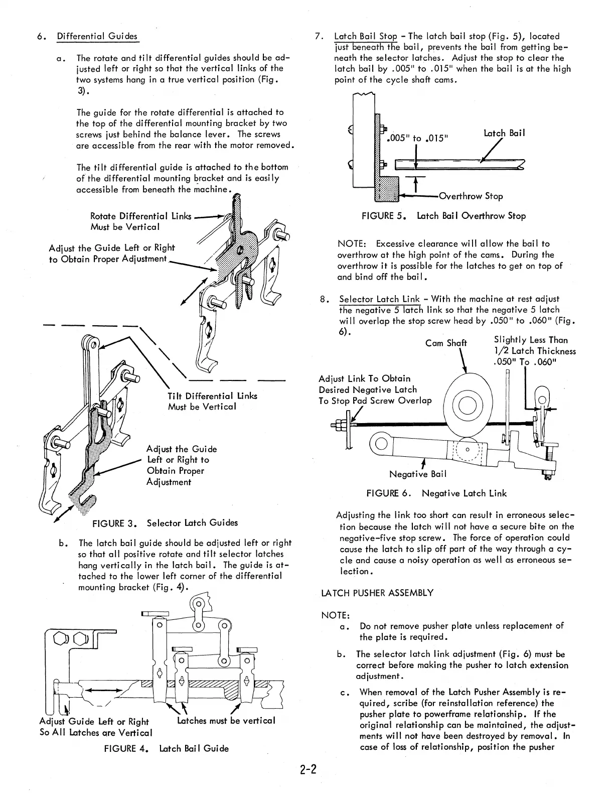
a.
The
rotate
and
tilt
differential guides should be
ad-
justed left or right so
that
the
vertical
links of
the
two systems hang in a true
vertical
position (Fig.
3).
The
guide for
the
rotate differential
is
attached
to
the
top of the differential mounting
bracket
by two
screws just behind the balance
lever.
The
screws
are
accessible
from
the
rear with
the
motor removed.
The
tilt
differential guide
is
attached
to
the
bottom
of'the
differential mounting bracket and
is
easi
Iy
accessible
from
beneath
the
~achine.
Rotate Differential links
__
~!0'i
Must be
Vertical
Adjust
the
Guide
left
or Right
to
Obtain
Proper Adjustment
Tilt Differential Unks
Must be
Vertical
Adjust
the
Guide
left
or Right
to
Obtain
Proper
Adjustment
FIGURE
3.
Selector
Latch Guides
b.
The
latch bail guide should be adjusted left or right
so
that
all
positive rotate and
tilt
selector
latches
hang
vertically
in the
latch
bail.
The
guide
is
at-
tached
to the lower left corner of the differential
mounting
bracket
(Fig. 4).
Adjust
Guide
left
or
Right
latches
must
be
vertical
So All
latches
qre
Vertical
FIGURE
4.
latch
Bai
I
Guide
7.
latch
Bail Stop
-The
latch bail stop
(Fig.
5),
located
just beneath
the
bail,
prevents the bail
from
getting
be-
neath the
selector
latches.
Adjust the stop
to
clear
the
latch bail by .005"
to
.015" when
the
bail is
at
the
high
point
of
the
cycle
shaft cams.
2-2
latch
Bail
/
-~
?
:::::::~~'"-..,;-._.n..,
..
rI·hrr'w
Stop
FIGURE
5.
latch
Bail Overthrow Stop
NOTE: Excessive
clearance
will
allow
the bail
to
overthrow
at
the high point of
the
cams. During the
overthrow
it
is
possible for the latches
to
get
on
top
of
and
bi
nd
off
the
bai I •
8.
Selector
latch
link
- With the machine
at
rest adjust
the
negative
5 latch link so
that
the
negative
5 latch
wi
II
overlap the stop screw head by .050"
to
.060" (Fig.
6).
Adjust
link
To
Obtain
Desired
Negative
latch
Cam Shaft
To
Stop Pad Screw
Overlap
I
Slightly
less
Than
1/2
latch
Thickness
.050"
To
.060"
FIGURE
6.
Negative
latch
link
Adjusting
the
I ink too short can result in erroneous
selec-
tion because
the
latch will not have a secure
bite
on the
negative-five
stop
screw.
The
force of operation could
cause the
latch
to
slip off part of
the
way through a
cy-
cle
and cause a noisy operation as well as erroneous
se-
lection.
LA
TCH
PUSHER
ASSEMBLY
NOTE:
a.
Do
not remove pusher
plate
unless replacement of
the
plate
is
required.
b.
The
selector
latch link adjustment
(Fig.
6) must
be
correct before making
the
pusher
to
latch
extension
adjustment.
c.
When removal of
the
Latch Pusher Assembly is
re-
quired,
scribe (for reinstallation reference)
the
pusher
plate
to
powerframe
relationship.
If
the
original relationship can be
maintained,
the
adjust-
ments
wi
II
not have been destroyed by remova
I.
In
case
of
loss
of
relationship, position
the
pusher

 Loading...


