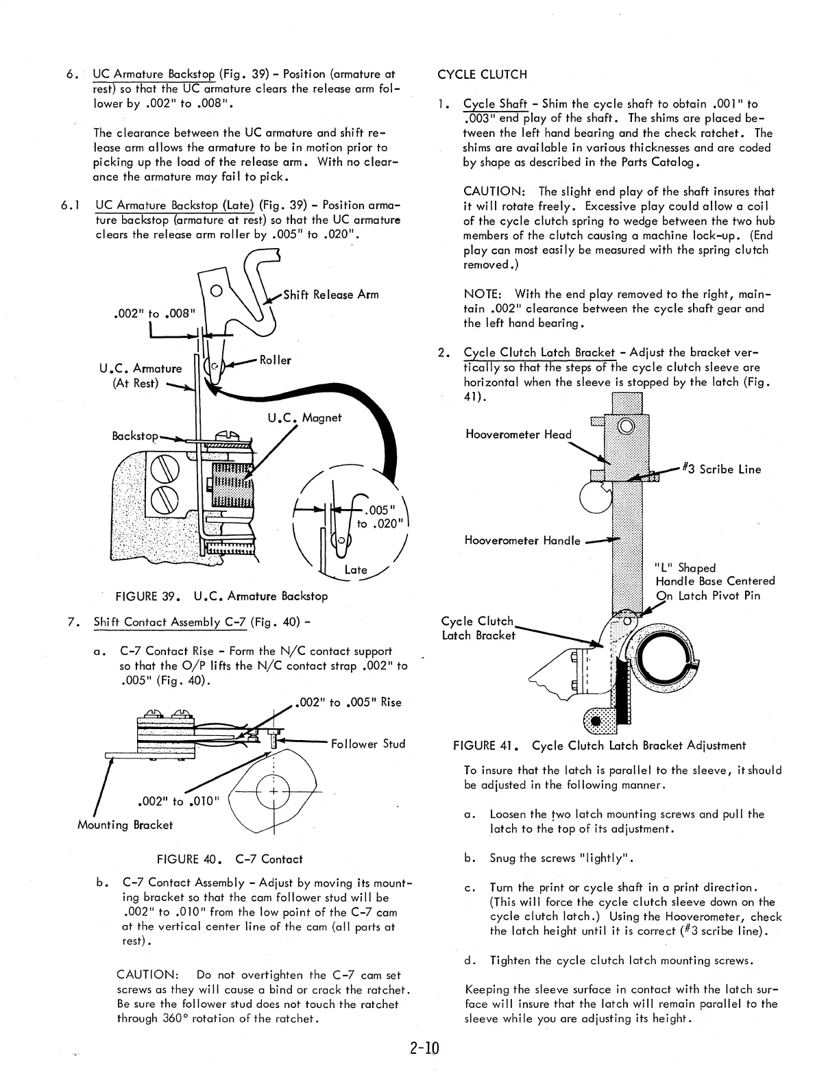
6.·
UC
Armature Backstop
(Fig.
39) - Positi
on
(armature
at
rest) so
that
the
UC
armature clears
the
release arm
fol-
lower by
.002"
to
.008".
The
clearance
between
the
UC
armature and shift
re-
lease arm allows
the
armature to
be
in motion prior
to
pi
cking up
the
load
of
the
release
arm.
With no
clear-
ance
the
armature may fai I
to
pick.
6.
I
UC
Armature Backstop (Late) (Fig. 39) - Position
arma-
ture backstop {armature
at
rest} so
that
the
UC
armature
clears
the release arm
roller
by
.005"
to
.020".
FIGURE
39.
U.C.
Armature Backstop
7.
Shift
Contact
Assembly
C-7
(Fig. 40) -
--
Lay
a.
C-7
Contact
Rise
-
Form
the
N/C
contact
support
so
that
the
alp lifts
the
NIC
contact
strap
.002"
to
.005"
(Fig.
40).
.002"
to
.005"
Rise
"'=!~~~~~~~~!~---
Follower Stud
Mounting Bracket
FIGURE
40.
C-7
Contact
b.
C-7
Contact
Assembly - Adjust by moving its mount-
ing
bracket
so
that
the
cam follower stud will
be
.002"
to
.010"
from
the
low point
of
the
C-7
cam
at
the
vertical
center
line of
the
cam (all parts
at
rest) •
CAUTION:
Do
not overtighten the
C-7
cam set
screws as they
wi
II
cause a bind or
crack
the
ratchet.
Be
sure the follower stud does not touch
the
ratchet
through 360
0
rotation
of
the
ratchet.
CYCLE
CLUTCH
I.
Cycle
Shaft -
Shim
the
cycle
shaft to obtain
.001"
to
.003"
end play
of
the
shaft.
The shims
are
placed
be-
tween
the
left hand
bearing
and
the
check
ratchet.
The
shims
are
available
in various thicknesses
and
are
coded
by
shape as described in
the
Parts
Catalog.
CAUTION:
The
slight
end
play
of
the
shaft insures
that
it
will
rotate
freely.
Excessive
play
could
allow
a coil
of
the
cycle
clutch
spring to wedge between
the
two hub
members
of
the
clutch
causing a machine
lock-up.
(End
play
can
most
easily
be measured with
the
spring clutch
removed.)
NOTE: With
the
end
play
removed
to
the
right I
main-
tain
.002"
clearance
between
the
cycle
shaft
gear
and
the
left hand
bearing.
2.
Cycle
Clutch Latch Bracket - Adjust the
bracket
ver-
tically
so
that
the
steps
of
the
cycle
clutch
sleeve
are
horizontal when
the
sleeve
is
stopped by
the
latch
(Fig.
41).
Hooverometer Handle
Cycle
C
Latch Bracket
"L" Shaped
Handle
Base
Centered
Latch Pivot
Pin
FIGURE
41.
Cycle
Clutch Latch Bracket Adjustment
To
insure
that
the
latch is parallel to
the
sleeve,
itshould
be adjusted in
the
following manner.
a.
Loosen
the
two
latch
mounting screws and pull the
.Iatch
to
the
top
of
its ad justment.
b.
Snug
the
screws
"lightly".
c.
Turn the print or
cycle
shaft in a print
direction.
(This will force the
cycle
clutch
sleeve down on
the
cycle
clutch
latch.)
Using
the
Hooverometer I
check
the
latch
height until
it
is
correct
{#3 scribe line}.
d.
Tighten the
cycle
clutch
latch
mounting screws.
Keeping
the
sleeve surface in
contact
with the
latch
sur-
face will insure
that
the
latch
will remain parallel to the
sleeve while you
are
adjusting its
height.
2-10