will
slightly
affect
the
adjustment
at
the
other
end.
Be
sure
to
recheck
each
adjustment.
Anvil
Frame
Power
______________
~*
Frame
Buffer
Anvil
Locking
Screws
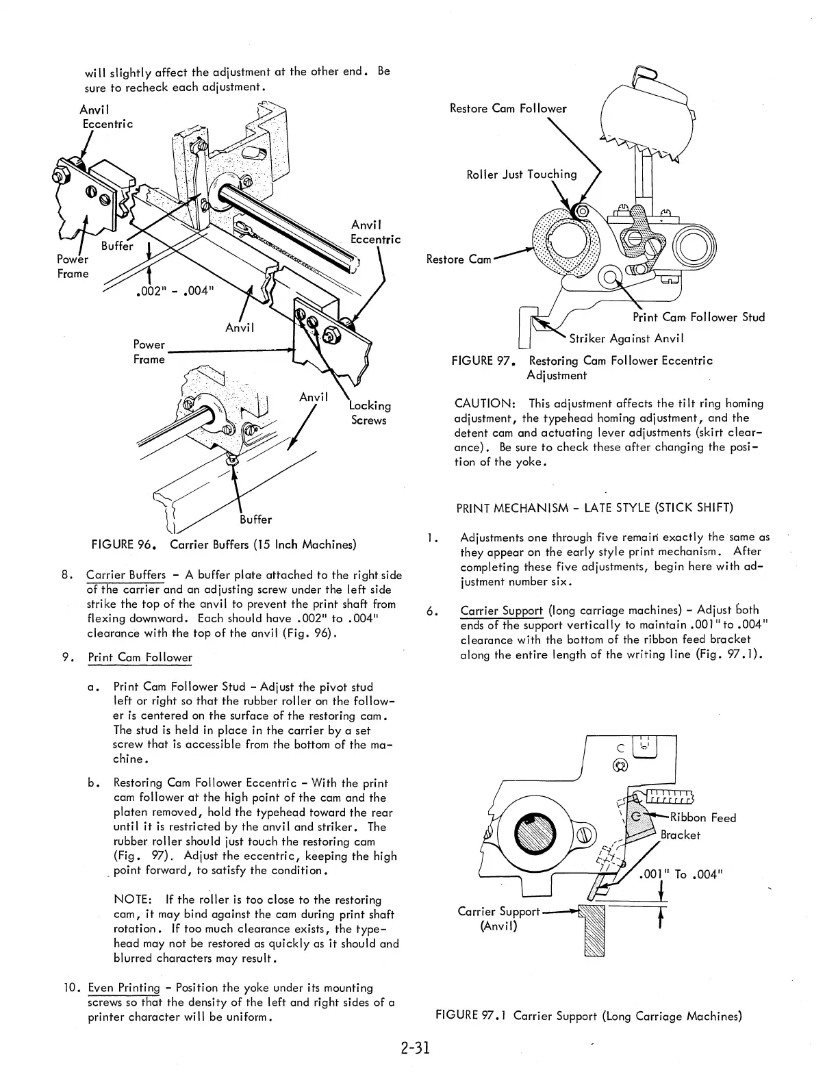
FIGURE
96.
Carrier
Buffers
(15
Inch Machines)
8.
Carrier
Buffers - A buffer
plate
attached
to
the right side
of
the
carrier
and an adjusting screw under
the
left
side
strike
the
top
of
the
anvil to prevent
the
print shaft
from
flexing downward. Each should
have
.002"
to
.004"
clearance
with
the
top
of
the
anvil
(Fig.
96).
9.
Print Cam Follower
a.
Print Cam Follower Stud - Adjust
the
pivot stud
left or right so
that
the
rubber roller on
the
follow-
er
is
centered
on
the
surface
of
the
restoring
cam.
The stud
is
held
in
place
in
the
carrier
by a
set
screw
that
is
accessible
from
the
bottom
of
the
ma-
chine.
b.
Restori
ng
Cam
Fo
II
ower Eccentri c -
Wi
th
the
pri nt
cam follower
at
the
high point
of
the
cam
and
the
platen
removed, hold
the
typehead
toward
the
rear
until
it
is
restri
cted
by the anvi I and
striker.
The
rubber roller should just touch
the
restoring cam
(Fig.
97). Adjust
the
eccentric,
keeping
the
high
_ point forward,
to
satisfy the
condition.
NOTE:
If
the
roller
is
too
close to
the
restoring
cam,
it
may bind
against
the cam during print shaft
rotation.
If too much
clearance
exists,
the
type-
head
may not be restored as
quickly
as
it
should and
blurred
characters
may
result.
10.
Even Printing - Position
the
yoke under its mounting
screws so
that
the
density
of
the
left and right sides
of
a
printer
character
wi
II
be uniform.
Restore
Cam
1.
6.
Striker Aga inst Anvi I
FIGURE
97.
Restoring Cam Follower Eccentric
Adjustment
CAUTION: This adjustment affects
the
ti It ring homing
adjustment,
the
typehead
homing
adjustment,
and
the
detent
cam and
actuating
lever
adjustments (skirt
clear-
ance).
Be
sure
to
check
these
after
changing
the
posi-
ti
on
of
the
yoke.
PRINT
MECHANISM -
LATE
STYLE
(STICK SHIFT)
Adjustments
one
through five remain
exactly
the same as
they
appear
on
the
early
style print mechanism.
After
completing
these
five adjustments, begin
here
with
ad-
justment number
six.
Carrier Support (long
carriage
machines) - Adjust both
ends
of
the
support
vertically
to maintain
.001"
to
.004"
clearance
with the bottom
of
the ribbon feed
bracket
along
the
entire
length
of
the writing
line
(Fig.
97.1).
.001"
To
.004"
!
t
FIGURE
97.
I
Carrier
Support (Long
Carriage
Machines)
2-31