are
set.
The
gang
clear
finger
can
be moved right
or
left
slightly
to
insure positive
clearing
of
desired
stop.
The
tab
stop
directly
to
the
left
may also be
cleared
or
partially
cleared.
TABULATOR
MECHANISM
(LATE)
I.
Interlock Switch (Fig.
161)
2.
a.
With the torque bar in the rest position,
form
the
horizontal
lug on
the
left
end
of
the tab
torque bar
so
that
.010" - .015" exists between
the
tabswitch
trigger
and
its
latching
surface.
b.
Tab
interlock
switch
bracket.
Adjust by its mount-
ing screws for two
conditions.
I.
Up
and
down so
that
the
torque bar
is
vertical
in the rest position.
Be
sure
that
torque bar
I inkage does not interfere when making this
adjustment.
2.
Front to
rear
so
that
.001" - .002"
clearance
exists
between
the tab switch trigger and the
rear
edge
of
the tab
torque
bar
extension.
3.
Adjust the switch by its mounting screws for
. 002" - .008"
clearance
between
the
switch
plunger and
trigger.
FIGURE
161. Tab Interlock Switch
(late)
Escapement Bracket (Fig.
98)
-
Observe
the .00
I"
-
.002"
clearance
between
the
escapement
bracket
and
the
tab
torque
bar.
If this adjustment
is
incorrect,
all
escapement
adjustments should be made before
proceed-
ing
wit~
the tab adjustments.
4.
5 •
6.
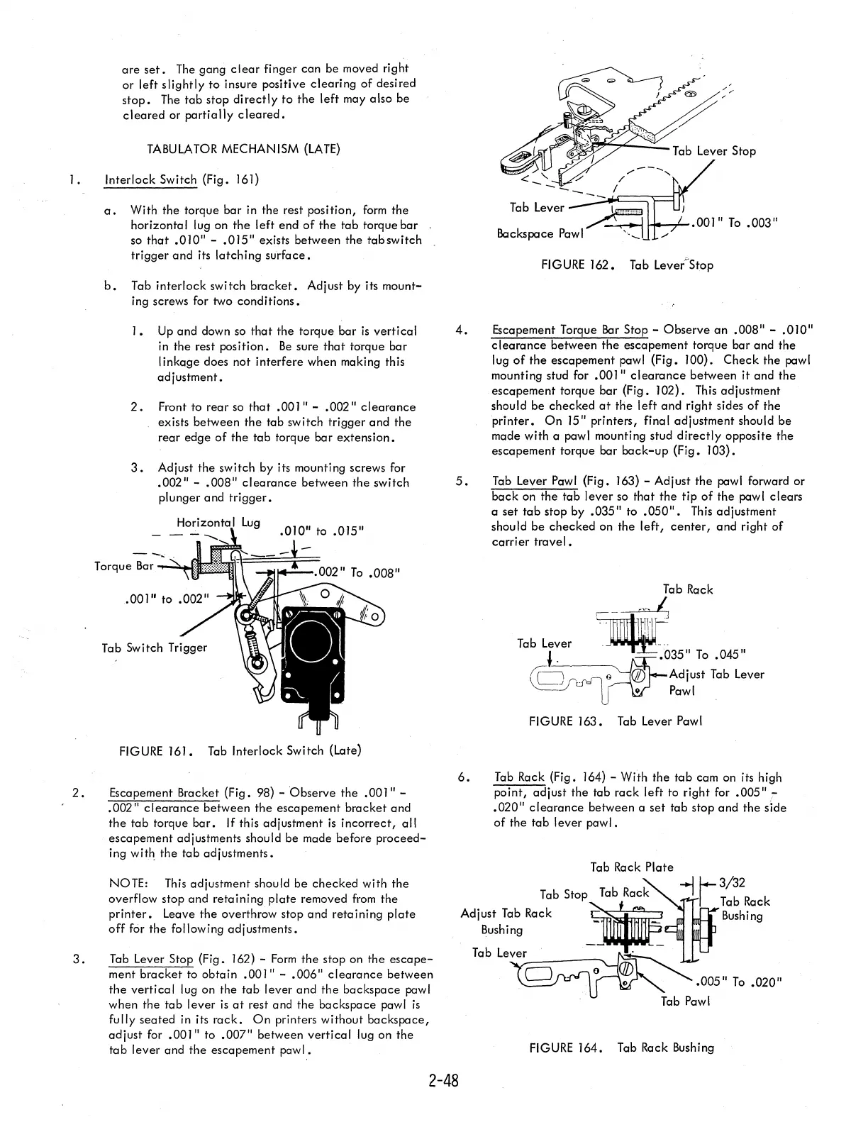
Tab Lever Stop
FIGURE
162. Tab Lever-Stop
Escapement Torque
Bar
Stop -
Observe
an
.008" - .010"
clearance
between
the
escapement
torque bar
and
the
lug
of
the
escapement pawl (Fig. 100).
Check
the pawl
mounting stud for .001"
clearance
between
it
and
the
escapement torque
bar
(Fig. 102).
This
adjustment
should be
checked
at
the
left
and
right sides
of
the
printer.
On
IS" printers, final adjustment should be
made with a pawl mounting stud
directly
opposite the
escapement torque bar
back-up
(Fig.
103).
Tab Lever Pawl (Fig.
163)
- Adjust
the
pawl forward or
back
on the
tab
lever
so
that
the
tip
of
the pawl clears
a
set
tab
stop by .035" to
.050".
This
adjustment
shou
Id
be
checked
on the
left,
center,
and right
of
carrier
travel.
Tab Rack
,---d
_
"
n-If-'-
Tab Lever -
~---
J _ .035"
To
.045"
~~AdjUst
Tab Lever
-=-V
d"
UV Pawl
FIGURE
J63. Tab Lever Pawl
Tab
Rack (Fig. 164) - With the
tab
cam on its high
point,
adjust
the tab
rack
left
to right for .005".:-
.020"
clearance
between a
set
tab
stop
and
the
side
of
the
tab
lever
pawl.
Tab Rack
Plate
NOTE:
This
adjustment should
be
checked
with the
overflow stop
and
retaining
plate
removed
from
the
printer.
Leave
the
overthrow stop and
retaining
plate
off
for
the
following adjustments.
~
1-3/32
Tab Stop
Tab
Rack
-I
I Tab Rack
Adjust Tab Rack
~
Bushing
Bushing
_~~
3.
Tab Lever Stop (Fig. J
62)
-
Form
the
stop on
the
escape-
ment
bracket
to
obtain
.OOJ"
- .006"
clearance
between
the
vertical
lug on the
tab
lever and
the
backspace pawl
when the
tab
lever
is
at
rest and the backspace pawl
is
fully
seated
in its
rack.
On
printers without
backspace,
adjust
for
.OOJ"
to .007" between
vertical
lug on the
tab
lever
and
the
escapement
pawl.
2-48
Table~~
jJ
o - . 0
~~
".005"
To
.020"
.
Tab
Pawl
FIGURE
164. Tab Rack Bushing