NOTE: Test this adjustment by manually
attracting
the
armature
and
turn ing the
operational
shaft
so
that
the
in-
terposer
is
being restored toward the front.
With
all
parts
at
rest
(Fig.
128
.6)
be
sure a
clearance
exists
between
the pull link
and
the
armature.
Interposer Latch Bracket
_rl~g~-----
Interposer Latch Position
Operational
Magnet
FIGURE
128.6
Trip Link
The pull
I ink must
be
approximately
1/2
turn too long to
insure
that
the armature
is
moving prior to picking up the
load
of
the
interposer • A
trip
I ink
adjusted
too short
can
cause
an
intermittent
operation
or
complete
failure to
re-
lease.
OPERATIONAL CONTACTS
1.
The interposer switch shall
be
adjusted
on
its mounting
bracket
so
that
the
top of
the
switch
is
flush with the
bottom
of
the
power frame
(Fig.
129).
OIP
FIGURE
129.
Operational
Contacts
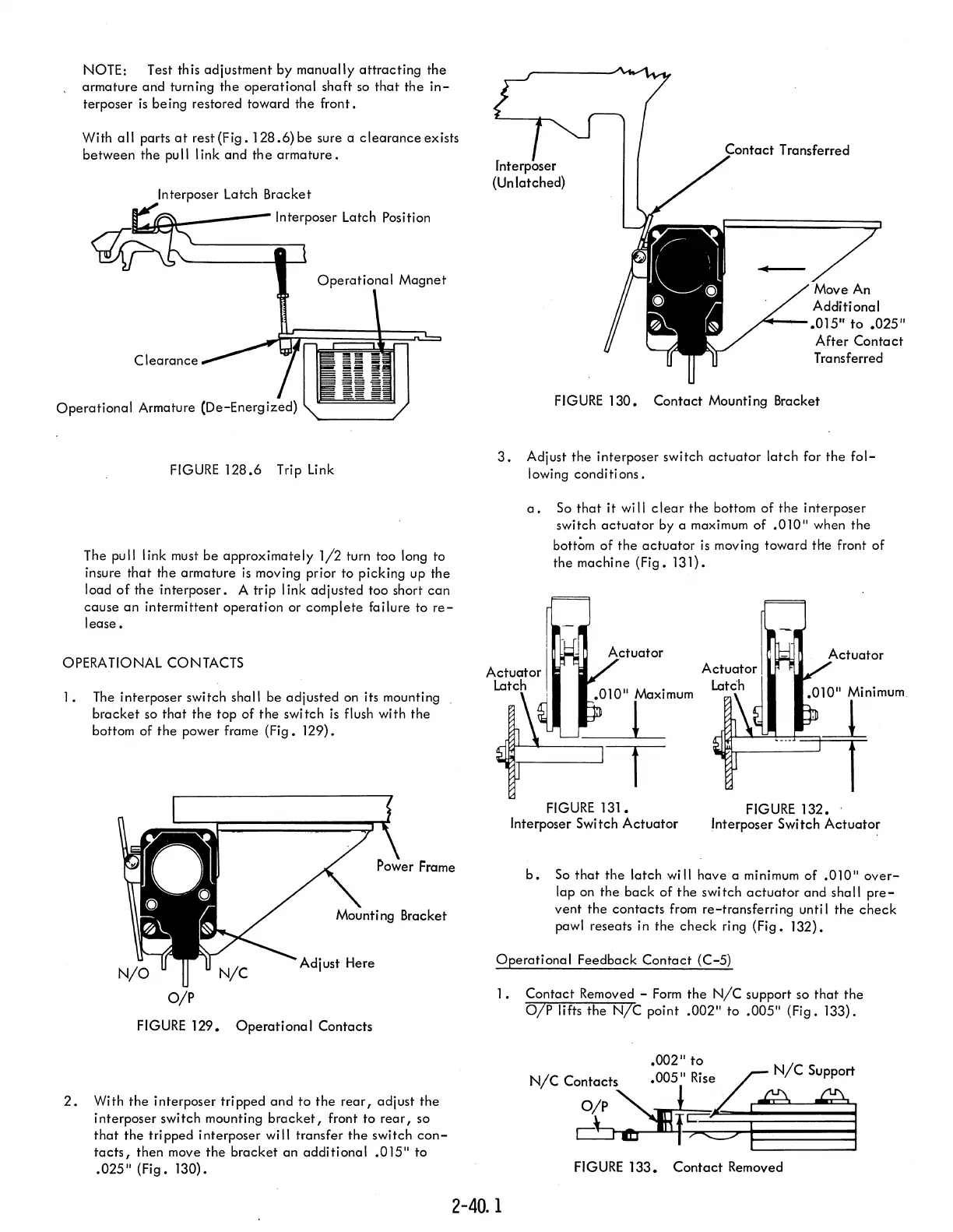
2.
With
the
interposer tripped
and
to
the
rear,
adjust
the
interposer switch mounting
bracket,
front to
rear,
so
that
the
tripped interposer will transfer
the
switch
con-
tacts,
then move
the
bracket
an
addi ti ona I
.015"
to
.025"
(Fig.
130).
fnterposer
(Un latched)
LnI'Tn'CT
Transferred
...........
--.015"
to
.025"
After
Contact
Transferred
FIG
URE
130.
Contact
Mounti
ng
Bracket
3.
Adjust
the
interposer switch
actuator
latch
for
the
fol-
lowing conditi ons.
a.
So
that
it
will
clear
the bottom
of
the interposer
switch
actuator
by a maximum
of
.010"
when
the
bottom
of
the
actuator
is
moving toward
the
front
of
the machine
(Fig.
131).
.010"
Maximum
1
T
FIGURE
131.
Interposer Switch
Actuator
.010"
Minimum
'~
FIGURE
132.
'
Interposer Switch
Actuator
b.
So
that
the
latch will have a minimum
of
.010"
over-
lap on the
back
of
the
switch
actuator
and
shall
pre-
vent
the
contacts
from re-transferring unti I the
check
pawl reseats in the
check
ring
(Fig.
132).
Operational
Feedback
Contact
(C-5)
1.
Contact
Removed -
Form
the
NIC
support so
that
the
OIP lifts
the
NIC point
.002"
to
.005"
(Fig.
133).
.002/1
to
005
/1
Ri'se~
NIC
Support
N/C
Ci~t2:F
e.
l
FIGURE
133.
Contact
Removed
2-40.
1