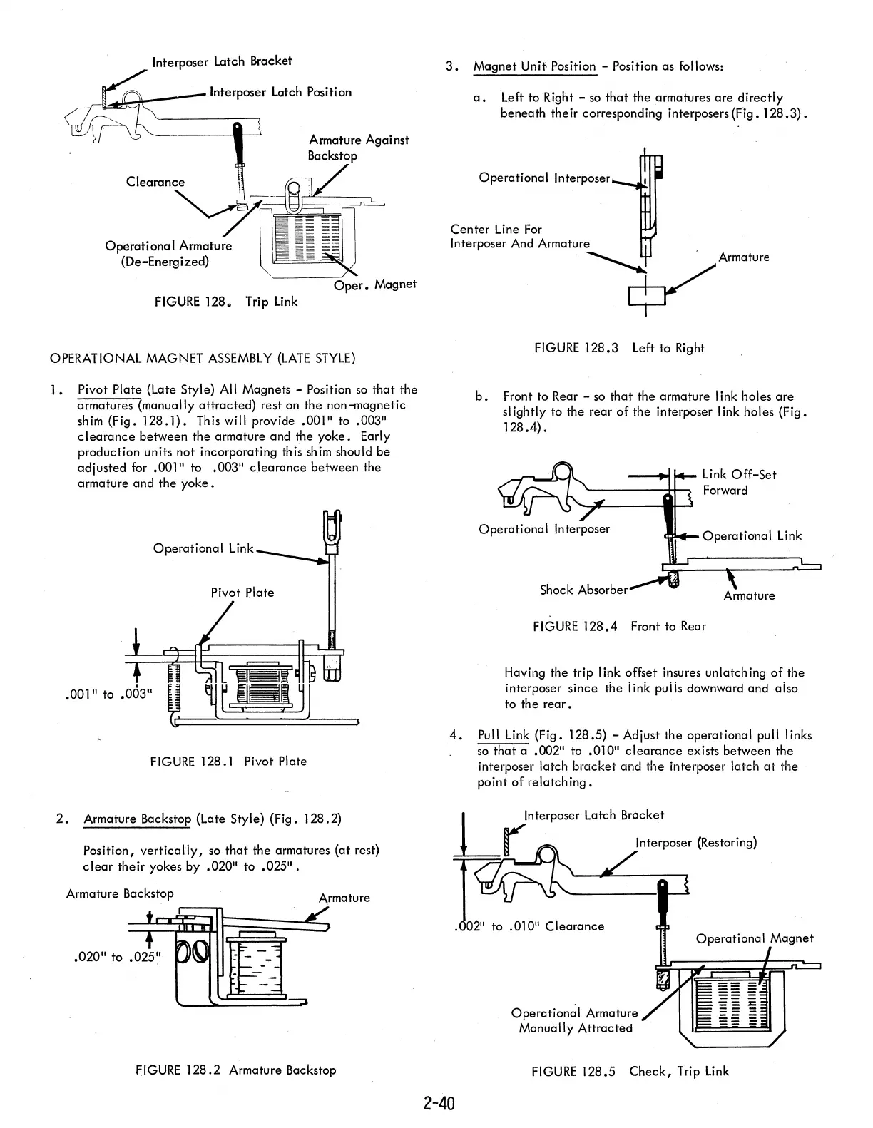
Interposer Latch Bracket
--,~~~~
___
Interposer Latch Position
Operational
Armature
(De-Energized)
FIGURE 128. Trip
Link
OPERATIONAL MAGNET
ASSEMBLY
(LATE
STYLE)
1.
Pivot
Plate
(Late Style) All Magnets - Position
so
that
the
armatures (manually
attracted)
rest on the
non-magnetic
shim
(Fig.
128.1). This will provide .001" to .003"
clearance
between
the
armature and the
yoke.
Early
production units
not
incorporating this shim should
be
adjusted
for .001" to .003"
clearance
between
the
armature
and
the
yoke.
Operational
Link
~_~
Pivot Plate
.001" to .003"
FIGURE
128.1 Pivot Plate
2.
Armature Backstop (Late Style)
(Fig.
128.2)
Position,
vertically,
so
that
the
armatures
(at
rest)
clear
their
yokes by .020"
to
.025".
Armature Backstop
Armature
fiGURE 128.2 Armature Backstop
3.
Magnet
Unit Position - Position as follows:
a.
Left to Right -
so
that
the armatures
are
directly
beneath
their
corresponding interposers
(Fig.
128.3).
Operational
Interposer
FIGURE
128.3 Left to Right
b.
Front to Rear -
so
that
the armature I ink holes
are
slightly
to the
rear
of
the interposer I ink holes
(Fig.
128.4).
Link
Off-Set
Shock Absorber
FIGURE
128.4 Front to Rear
Having the trip
I ink offset insures unlatch ing
of
the
interposer
since
the iink puiis downward and aiso
to
the
rear.
4.
Pull Link (Fig. 128.5) - Adjust the
operational
pull links
so
that
a .002" to .010"
clearance
exists between
the
interposer latch
bracket
and
the
interposer latch
at
the
point
of
relatch
ing.
2-40
Operational
Armature
Manually
Attracted
FIGURE
128.5
Check,
Trip Link