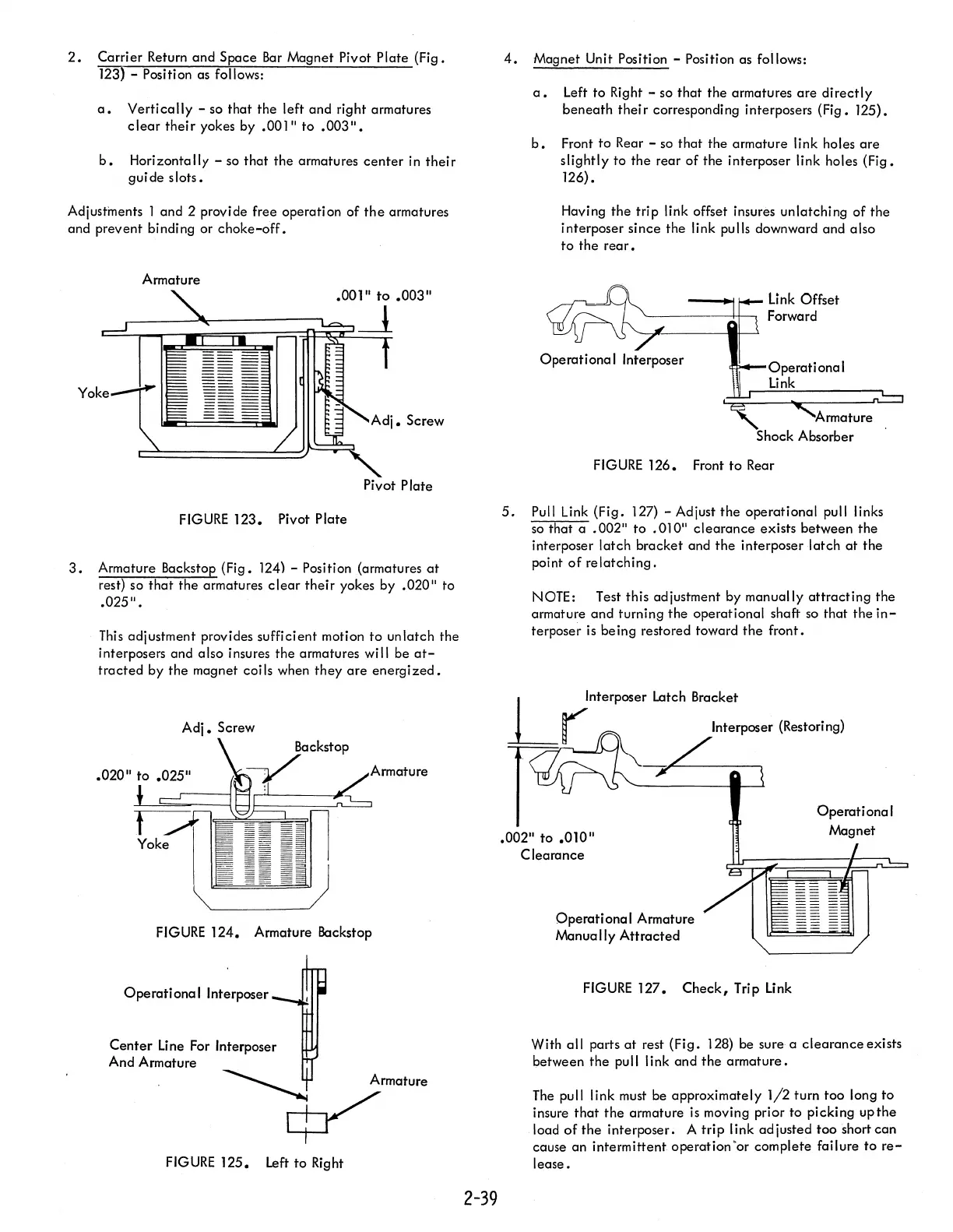
2.
Carrier Return and Space
Bar
Magnet Pivot Plate (Fig.
123)
- Position as follows:
a.
Vertically
- so
that
the left and right armatures
clear
their
yokes by .001"
to
.003".
b.
Horizontally - so that
the
armatures
center
in
their
guide
slots.
Adjustments 1 and 2 provide free operati
on
of
the
armatures
and prevent binding or
choke-off.
Armature
Pivot Plate
FIGURE
123. Pivot Plate
3.
Armature Backstop (Fig.
124)
- Position (armatures
at
rest) so
that
the armatures
clear
their
yokes by .020" to
.025".
This
adjustment provides sufficient motion
to
unlatch the
interposers and
also insures
the
armatures will be
at-
tracted
by
the
magnet coils when
they
are
energized.
Armature
FIGURE
124. Armature Backstop
Operational
Interposer
Center
line
For Interposer
And Armature
FIGURE
125.
Left
to
Right
2-39
4.
Magnet Unit Position - Position as follows:
a.
Left to Right - so
that
the armatures
are
directly
beneath
their
corresponding interposers (Fig. 125).
b.
Front
to
Rear - so that the armature link holes
are
slightly
to
the
rear of the interposer link holes (Fig.
126).
Having
the
trip link offset insures unlatching of
the
interposer since the link pulls downward and also
to
the
rear.
FIGURE
126. Front
to
Rear
5.
Pull Link (Fig.
127)
- Adjust
the
operational pull links
so
that a
.002"
to
.010"
clearance
exists between
the
interposer
latch
bracket and
the
interposer latch
at
the
point
of
relatching.
NOTE: Test this adjustment by manually
attracting
the
armature
and
turning the operational shaft so that
the
in-
terposer
is
being restored toward
the
front.
.002"
to
.010"
Clearance
Operational
Armature
Manually
Attracted
FIGURE
127.
Check,
Trip
link
Operational
Magnet
With all parts
at
rest (Fig.
128)
be sure a
clearance
exists
between the
pu
II
link and
the
armature.
The
pull link must be approximately
1/2
turn too long
to
insure
that
the
armature is moving prior
to
picking
upthe
load
of
the
interposer. A
trip
link adjusted too short can
cause an intermittent operation
'or
complete fai lure
to
re-
lease.