Excessive
Band
Wi
dth Between
o (zero) and -1
-3
and
+5
-3,
+5
and
0 (zero)
-5
and
-3
Cause
Incorrect
balance
Incorrect
rotate
arm motion
Incorrect
latch
clearances
Incorrect paddle adjustment
Unwanted compensator roller droppage may result from
one
or more
of
the
following.
a.
Improper
detent
timing
b.
Malselection
(popping latches)
c.
Incorrect
rotate
spring tension
or
damper spring
ten-
sion.
d.
Binds in
the
typehead,
upper ball
socket,
rotate
shaft,
rotate
pulley,
or
rotate
spring.
e.
Binds in
the
compensator
or
lever
system.
f. Loose
differential
mounting
bracket.
g.
Excessive band width or
head
play.
If
the
band width appears
to
be
all
right but
the
align-
ment
is
not
satisfactory,
check
the
following items:
a.'
Detent timing
b.
Play or binds in
the
tilt
or
rotate
detents.
Side
play
in
the
rotate
detent
can
be
checked
by
repeating
any
full
size
character
such as
the
letter"
N"
so
that
it
repeats
for a full
line.
Move
the
carrier
backman-
ually
and
repeat
the
operation
without
indexing.
The
second line should
cover
the
first line
exactly.
If
any
of
the
characters
are
shadowed, side
play
in
the
rotate
detent
could
be the
cause.
c.
Loose fitting upper
ball
socket
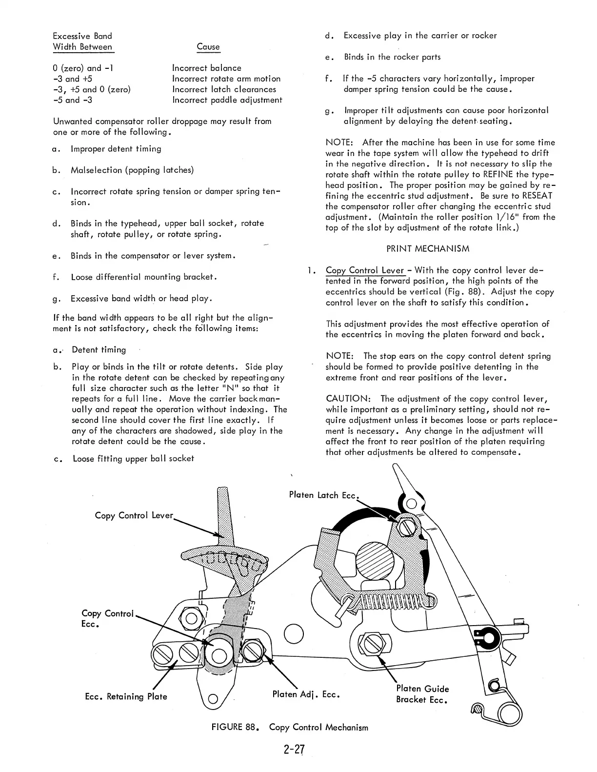
Copy Control Lever
Copy Control
Ecc.
d.
Excessive
play
in
the
carrier
or rocker
e.
Binds
in the rocker parts
f.
If
the
-5
characters
vary
horizontally,
improper
damper spring tension cou
Id
be
the
cause.
g.
Improper ti
It
adjustments
can
cause
poor
horizontal
alignment by
delaying
the
detent,
seating.
NOTE: After
the
machine
has been in use for some time
wear in
the
tape
system will
allow
the
typehead
to
drift
in
the
negative
di recti
on.
It
is
not necessary
to
slip
the
rotate
shaft within
the
rotate
pulley
to
REFINE
the
type-
head
position.
The proper position may be
gained
by
re-
fining the
eccentric
stud
adjustment.
Be
sure
to
RESEAT
the
compensator
roller
after
changing
the
eccentri
c stud
adjustment.
(Maintain
the
roller
position
1/16"
from
the
top of the
slot
by adjustment
of
the
rotate
link.)
PRINT MECHANISM
1.
Copy Control Lever - With
the
copy control
lever
de-
tented
in
the
forward
position,
the
high points
of
the
eccentrics
should be
vertical
(Fig.
88).
Adjust
the
copy
control
lever
on
the
shaft
to
satisfy this
condition.
This
adjustment provi des
the
most
effective
operation
of
the
eccentri
cs
in moving
the
platen
forward
and
back.
NOTE: The stop ears on
the
copy control
detent
spri
ng
should be formed
to
provide positive
detenting
in
the
extreme front
and
rear
positions
of
the
lever.
CAUTION: The adjustment
of
the
copy control
lever,
while important as a preliminary
setting,
should not
re-
quire
adjustment unless
it
becomes loose or parts
replace-
ment
is
necessary.
Any
change
in
the
adjustment will
affect
the front
to
rear
position of
the
platen
requiring
that
other adjustments be
altered
to
compensate.
FIGURE
88.
Copy Control Mechanism
2-27