not occurring
at
the
negative
four position, thus
the
arm
assembly
is
operating as one soli d arm
at
this position.
In
Figure 85C
the
correct amount
of
rati 0
change
is in
the
system. All positions
from
the
-3
to
the
+5
detent
the
same as
the
-5.
Note
that
when
the
-3
detents
the
same as
the
-5,
the detenting
of
the
-4
is
slightly
dif-
ferent.
This
is
caused by the ratio
change.
No
attempt
should be made to control
the
detenting
of
the
-4
posi-
tion because its position may vary
on
each
machine
de-
pending
on
the
amount of ratio change required (of
each
machine)
to
make
the
-3
detent
the same as
the
-5.
13.
Print.Shaft Timing (Final) - Advance or retard the print
shaft
relative
to
its gear
to
obtain the proper timing
of
the
rotate
detent.
Hand-cycle
an upper case
-5
char-
acter
and observe the rotate
detent
as it operates in the
typehead
notch.
The
detent
must
enter
the
correct
de-
tent
notch
and
withdraw without restricting
the
restoring
of
the
typehead.
There should be
.002"
to
.004"
back-
lash
felt
in
the
type head when the
detent
is
near
the
bottom
of
the
s lope of
the
detent
notch
(Fig.
86).
Typehead Restoring
~
t
FIGURE
86.
Withdrawal
Clearance
For The
-5
Character
After adjusting
the
timing
of
the
rotate
detent
to
the
up-
per case
-5
character,
check
the
detent
entry
and
with-
drawa I of
an
upper case
+5
character.
If
the
detent
re-
stricts
the
typehead
from
restoring
on
withdrawal when
the
+5
is slowly
hand-cycled,
advance
the
print shaft
slightly
until
the
+5
has a withdrawal backlash of
.002"
to
.004".
When
the
withdrawal adjustment has been
completed check the
detent
entry on both
the
+5
and
-5.
The
detent
must
enter
the correct
notch.
CAUTION: After
hand-cycling
the
machine
the
com-
pensator roller must be raised
to
the
top
of
the
wedging
slot
and
reseated under power by striking a series
of
-5
cha
racters.
If
difficulty
is
encountered in obtaining the correct
de-
tent
timing,
check
the
following items:
a.
Detent ski
rt
clearance
- favor
the
high side
of
the
tolerance.
b.
Typehead homing - favor
the
high side
of
the
tol-
erance.
c.
Band width - make sure
that
it
is
not
excessive.
2-26
d.
Head play -
it
should be
.045"
measured
at
the
type head
skirt.
If excessive head play is suspected
the
ball joint should be
replaced
and
the
typehead
homing adjustment
refined.
CAUTION: Excessively
advanced
or retarded timing
can
cause parts damage as well as poor horizontal
align-
ment
or
improper
selection.
This
could happen
if
the
detent
entered
the
wrong notch or remai ned in
the
notch
too long.
NOTE:
Be
sure
to
maintain
.002"
to
.004"
end
play in
the
pri nt
shaft.
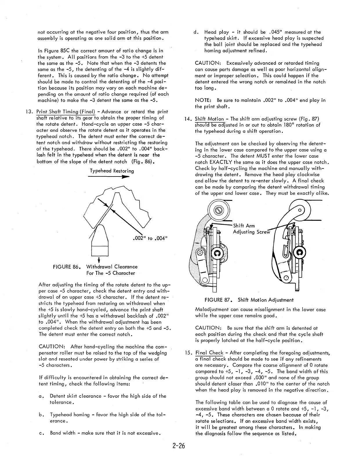
14.
Shift Motion -
The
shift arm adjusting screw (Fig. 87)
should be adjusted in or out to obtain
180
0
rotation
of
the
typehead
during a shift
operation.
The
adjustment can be
checked
by observing
the
detent-
ing in
the
lower case compared
to
the
upper case using a
-5
character.
The
detent
MUST
enter
the
lower case
notch
EXACTLY
the
same as
it
does the upper case
notch.
Check by
half-cycling
the machine
and
manually
with-
drawing
the
detent.
Remove
the
head play clockwise
and
allow
the
detent
to
re-enter
slowly.
A final
check
~an
be made by comparing
the
detent
withdrawal timing
of
the
upper and lower
case.
They must be
exactly
alike
•
.1:"'--_
Sh
i ft
Arm
Adjusting Screw
...
~
FIGURE
87.
Shift Motion Adjustment
Maladjustment can cause misalignment in
the
lower case
while the upper case remains
good.
CAUTION:
Be
sure
that
the shift arm is detented
at
each
position during the
check
and
that
the
cycle
shaft
is properly latched
at
the
half-cycle
position.
15.
Final Check - After completing
the
foregoing adjustments,
a final
check
should be made
to
see
if
any
refinements
are
necessary. Compare
the
coarse alignment of 0
rotate
compared
to
+5,
-1, -3,
-4, -5.
The
band width
of
this
group should not
exceed
.030"
and none
of
the
group
should
detent
closer than
.010"
to
the
center
of
the
notch
when the head play
is
removed in the
negative
direction.
The
following
table
can be used
to
diagnose
the
cause
of
excessive band
wi
dth between a 0 rotate and
+5,
-1,
-3,
-4, -5.
These characters
are
chosen because
of
thei r
rotate
se lecti ons. If an excessive band
wi
dth exists,
it
wi
II
be
greatest
among these
characters.
In
making
the
diagnosis follow
the
sequence as
listed.