NOTE:
If
necessary, refine
the
pivot eccentric adjustment.to
ob-
tain equal latch lever overthrow
from
the
T2
and
R5
arm-
atures (Fig. 14). Adjustment
No.6,
Page
1-4.
4.
Cycle Clutch Latch Restoring (Fig. 21) - Position the
re-
storing roller so
that
the trip lever overthrows
trcalatch
lever by
.005"
to
.010"
at
its latching point on"'the low
side of the restoring
cam.
::::::.~~r-
___
-IAdjust
Here
(Up
or
Down)
\.,,"""--
Restoring Cam
.005"
to
.010"
Overthrow
FIGURE
21.
Restoring Roller
5.
Cycle Clutch Latch Inhibitor (New) :
a.
Adjust the inhibitor trip lever (Fig. 22) so
that
the
bottom edge
of
the inhibitor pawl
is
flush with the
bottom edge
of
the
cycle
clutch latch (Fig.
26)
with
a
II
parts
at
rest.
This
adjustment provides an adequate
"bite"
be-
tween the
cycle
clutch
latch and inhibitor pawl
to
prevent extra
cycles.
.
Adjusting
Screw
FIGURE
22.
Inhibitor
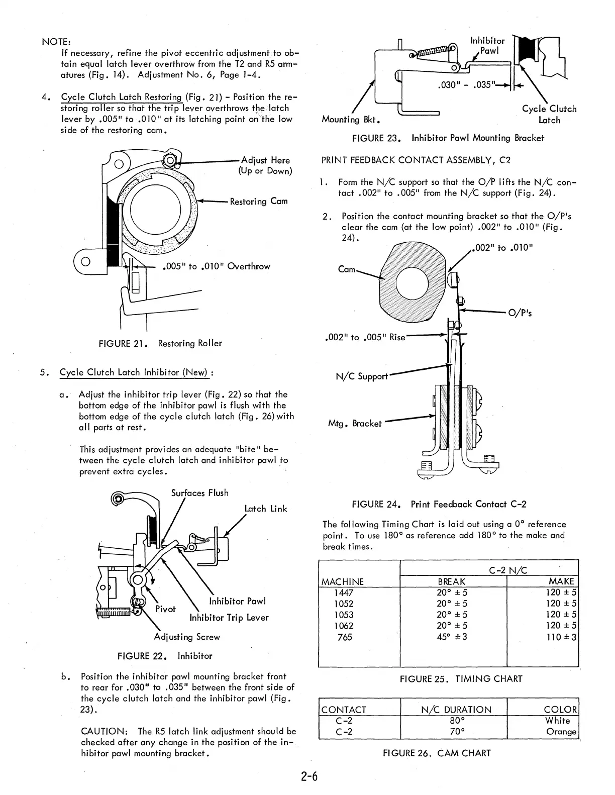
b.
Position
the
inhibitor pawl mounting bracket front
to
rear for
.030"
to
.035"
between the front side of
the
cycle
clutch latch and the inhibitor pawl (Fig.
23).
CAUTION:
The
R5
latch link adjustment should be
checked
after
any
change in
the
position of the
in-
hibitor pawl mounting
bracket.
2-6
FIGURE
23.
Inhibitor Pawl Mounting Bracket
PRINT
FEEDBACK
CONTACT
ASSEMBLY,
C2
I.
Form
the
N/C
support
so
that the
O/P
lifts the
N/C
con-
tact
.002"
to
.005"
from
the
N/C
support (Fig. 24).
2.
Position the
contact
mounting bracket
so
that
the
O/p's
clear
the cam (at the low point)
.002"
to
.010"
(Fig.
24)
•
002"
to
.010"
Cam
t----O/P's
Mtg.
Bracket
FIGURE
24.
Print Feedback Contact
C-2
The following Timing Chart
is
laid out using a
0°
reference
point.
To
use
180° as reference add 180° to the make and
break times.
C-2
N/c
MACHINE
BREAK
MAKE
1447
20°
±5
120 ± 5
1052
20°
±5
120
±5
1053
20°
± 5
120 ± 5
1062
20°
± 5
120
±5
765
45°
±3
110±3
FIGURE
25.
TIMING
CHART
CONTACT
N/C
DURATION
COLOR
(-2
80°
White
C-2
70°
Orange
FIGURE
26.
CAM
CHART
,
,