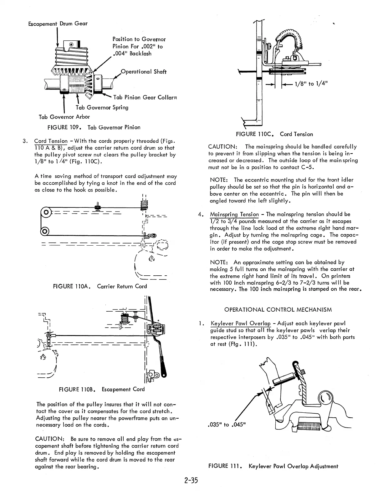
Position
to
Governor
Pinion For
.00211
to
.004
11
Backlash
Operational
Shaft
Tab Pinion
Gear
CollarR
Tab Governor Spring
Tab Governor Arbor
FIGURE
109.
Tab Governor Pinion
3.
Cord Tension - With
the
cords properly threaded (Figs.
110 A &
B)
I adjust the
carrier
return cord drum
so
that
the
pulley
pivot screw nut clears the
pulley
bracket by
1/8"
to
1/4"
(Fig. I1OC).
A time saving method
of
transport card adjustment may
be accomplished by tying a knot in the end of the cord
as close
to
the hook as possible.
II
I
,I
.~-._'.
- -
--
-
--
---.-
'r-)
-
--
-----
___
--
JII--f
,I
,
,,~
,)'-~
-
(
L~--
~
\'--
--
---
FIGURE
1 lOA. Carrier Return Cord
il
,
_...J..J_
..JI
-
---,.
Ii
)
''''''
=l
\,-
------
--
- .
.
\~---------:
~~
I
-
e..
\~~
I
b \ I
4 I
=::/
I~
FIGURE
110B. Escapement Cord
The
position of
the
pulley
insures
that
it
wi
II
not
con-
tact
the
cover
as
it
compensates for
the
cord
stretch.
Adjusting
the
pulley
nearer the powerframe puts an
un-
necessary load on
the
cords.
CAUTION:
Be
sure
to
remove
all
end play
from
the
dS-
capement shaft before tighteni
ng
the
carri
er
return cord
drum.
End
play is removed by holding
the
escapement
shaft forward while
the
cord
drum
is moved
to
the
rear
against
the
rear
bearing.
2-35
"
FIGURE
110C.
Cord Tension
CAUTION: The mainspring should be handled carefully
to prevent
it
from
sl
ipping when
the
tension
is
being
in-
creased or
decreased.
The outside loop
of
the main spring
must
not be in a position to
contact
C-5.
NOTE:
The
eccentric
mounting stud for
the
trontidler
pulley should be
set
so
that
the
pin is horizontal and
a-
bove
center
on
the
eccentri
c.
The
pin will then be
ang led toward the left
slightly.
4.
Mainspring Tension -
The
mainspring tension should be
1/2
to
3/4
pounds measured
at
the
carrier
as
it
escapes
through
the
line lock load
at
the
extreme right hand
mar-
gin.
Adjust by turning the mainspring
cage.
The
capac-
itor (if present) and the
cage
stop screw must
be
removed
in order
to
make
the
adjustment.
NOTE: An approximate setting
can
be obtained by
making 5 full turns on the mainspring with the
carrier
at
the extreme right hand limit of its
travel.
On
printers
with 100 inch mainspring
6-2/3
to
7-2/3
turns will be
necessary.
The
100 inch mainspring is stamped on the
rear.
OPERATIONAL CONTROL MECHANISM
1 • Keylever Pawl
Overlap
- Adjust
each
keylever
pawl
guide stud so
that
all
the keylever pawls
verlap
their
respective interposers by
.035"
to
.045"
with both parts
at
rest
(Fig.
111) .
FIGURE
111.
Keylever Pawl
Overlap
Adjustment