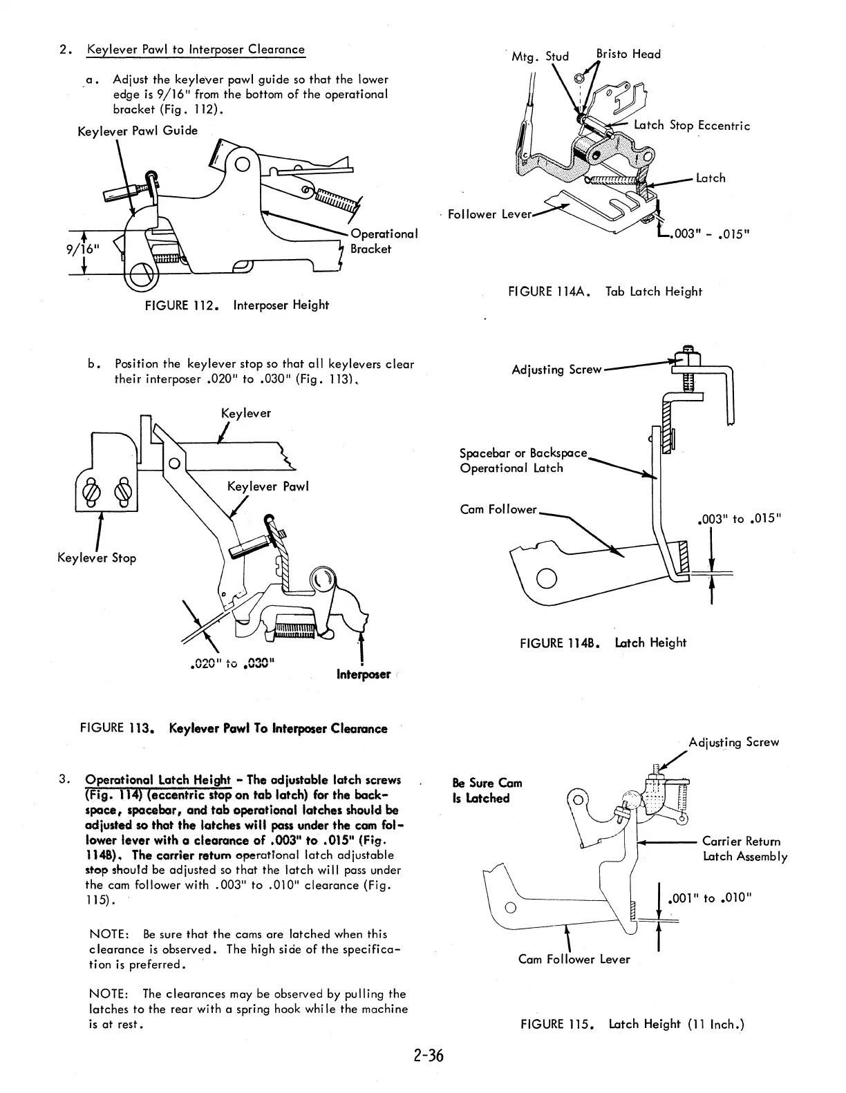
2.
Keylever
Pawl
to Interposer Clearance
a.
Adjust the keylever pawl guide
so
that the lower
edge
is
9/16"
from
the bottom of the operational
bracket (Fig. 112).
Keylever
Pawl
Guide
Bristo Head
latch
. Follower
FIGURE
112.
Interposer Height
b.
Position the key lever stop
so
that
all
keylevers
clear
their interposer .020" to .030" (Fig. 113).
n",n
II.L_
n"2l\l1
•
U~V
IV
.u'-'V
.
Interposer (
FIGURE
113. Keylever
Powl
To
Interposer Clearance
3.
Operational
Latch Height - The odjustable
latch
serews
(Fig.
114)
(eccentric
stop
on
tab
latch) for
the
back-
space,
spacebar,
and
tab
operational latches should
be
adjusted so thot
the
latches
will
pass under
the
cam
fol-
lower lever with a
clearance
of
.003" to .015" (Fig.
1146). The
carrier
retum operational latch adjustable
stop should be adjusted
so
that the latch
wi
II
pass under
the
cam follower with .003" to .010" clearance (Fig.
115) .
NOTE:
Be
sure that the cams are latched when this
clearance
is
observed. The high side of the
specifica-
tion
is
preferred.
NOTE:
The
clearances may be observed by pulling the
latches to the rear with a spring hook
whi
Ie
the machine
is
at
rest.
2-36
003" -
.015"
FIGURE
114A.
Tab
Latch Height
Adjusting
Screw----C:;===~
Spacebar or Backspace
Operational Latch
.003" to .015"
~
T
FIGURE
1148. Latch Height
Be
Sure
Cam
Is
Latched
Cam
Follower Lever
Adjusting Screw
~---
Carrier Return
latch
Assemb
Iy
~Olll
to .010"
-r
FIGURE
115. Latch Height
(11
Inch.)