4.
Interposer Adjusting Screws - Adjust the interposer
ad-
justing screws
so
that
a front to rear
clearance
of
.015"
to .020" exists between
all
the operational latches and
their respective cam followers, with the exception
of
the spacebar
latch.
The
spacebar
latch should have a
clearance
of
.025" to .035" (Fig. 116).
NOTE: Machines which have the
carrier
return
latch-
spring loaded to
the
rear (under
the
cam follower) should
be adjusted as follows:
a.
Hold
the
carrier
return latc.h to
the
front against its
interposer (the interposer should be latched
at
rest).
b.
Adjust the interposer adjusting screw for
.035"
to
.045"
between
the
lotch and cam follower.
c.
Release the interposer
and
proceed with
the
next
adjustment.
Cam Follower
I.£Itch
Make Adjustment Here
Interposer
FIGURE
116.
Interposer Adjusting Screw
NOTE:
The
operational interposer springs should be
placed
in
the
center
hole
at
the rear
of
the interposer
(Fig. 116).
The
adjustment
directly
affects
the
timing between the
cam release and
the
positioning
of
the
operational
latches under the cam
follower.
Excessive
clearance
can
a
II
ow
the cam follower
to
move down
at
the rear before
the
latch has moved fully under
the
follower.
The
adjustment may be
checked
after
operating the cams
enough to move
the
cam followers down slightly
at
the
rear.
With the machine on its back
the
latches can be
pushed against
the
cam followers
to
estimate
the
clear-
ance.
CAUTION:
If
the
cam followers
are
operated too far
when this adjustment
is
being
checked,
the interposer
restoring bail will force
the
interposers forward slightly
and an erroneous adjustment will
result.
The
keylever
pawl
to
interposer
clearance
should be rechecked
after
this adjustment.
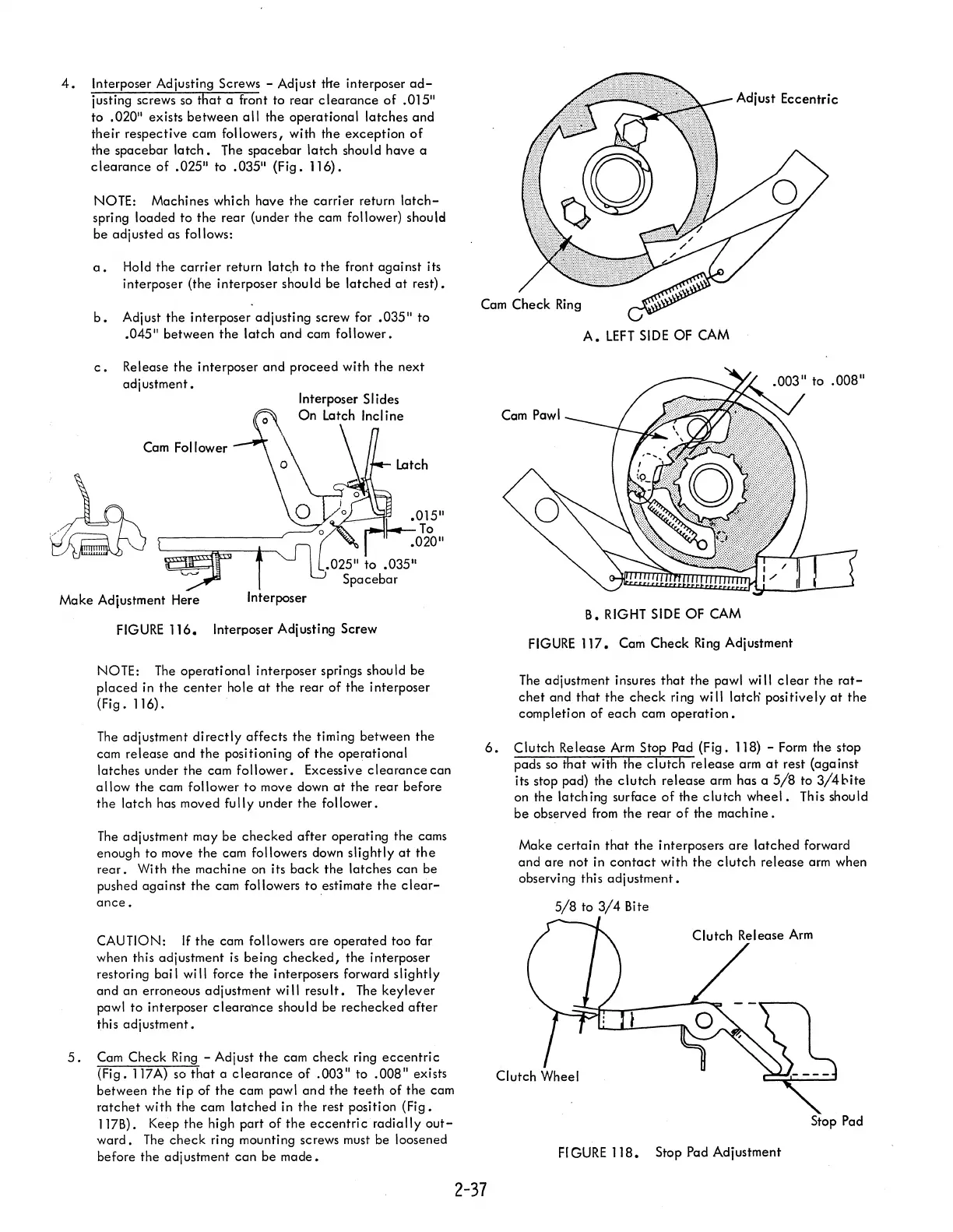
5.
Cam Check
Ring
- Adjust
the
cam check ring
eccentric
(Fig. 117A) so
that
a
clearance
of
.003"
to
.008"
exists
between
the
tip
of
the
cam pawl
and
the
teeth
of
the
cam
ratchet
with
the
cam
latched
in
the
rest position (Fig.
117B). Keep
the
high
part
of
the
eccentric
radially
out-
ward.
The
check
ring mounting screws must be loosened
before
the
adjustment
can
be
made.
Adjust Eccentric
A.
LEFT
SIDE
OF CAM
B. RIGHT
SIDE
OF CAM
FIGURE
117.
Cam Check
Ring
Adjustment
The
adjustment insures
that
the pawl will
clear
the
rat-
chet
and
that
the
check
ring will latch' positively
at
the
completion
of
each
cam
operation.
6.
Clutch Release
Arm
Stop Pad (Fig. 118) -
Form
the
stop
pads
so
that
with the
clutch
release arm
at
rest (against
its stop pad) the
clutch
release
arm has a
5/8
to 3/4l:-ite
on the latching surface
of
the
clutch
wheel.
This should
be
observed
from
the
rear
of
the
machine.
2-37
Make
certain
that
the
interposers
are
latched
forward
and
are
not in
contact
with
the
clutch
release arm when
observing this
adjustment.
5/8
to
3/4
Bite
Stop Pad
FIGURE
118.
Stop Pad Adjustment