7.
8.
'"
The
support
is
secured to the machine power frame by
two binding screws
at
each
end.
Elongated holes
inthe
machine powerframe enables the support to be adjusted
vertically.
This
adjustment serves the same purpose as
the
carrier
buffers on the
early
level machines.
Print Cam Follower Stop Screw - Adjust the cam
follow-
er
stop screw so
that
the
print cam follower roller clears
the
print cam by
.020"
when the machine
is
at
rest (Fig.
97.2).
This
clearance
ensures that the rocker will
re-
store fully on
every
cycle.
,--,,--\
I
'-
- -
--
___
_
FIGURE
97.2
Print Cam Follower Stop Screw
Printers With Impression Control (Stick Shift)
a.
Powered Travel - With the
cycle
shaft latched
at
rest
and
the impression control lever
set
at
position
5 and the copy control lever
set
at
5 (all the way
back), loosen the binding screw and move
the
de-
tent
plate
forward or backward unti I a
clearance
of
.250"
exists
between
the
platen
and
the
center
of
the "home"
character
(Fig.
97.3).
This
clearance
may be measured with the foot
of
the Hooverometer
which
is
approximately
.250".
When measuring
the
adjustment, remove
the
tilt
ring play
by
de-
pressing
the
typehead I ightly toward the front
of
the
machine.
Hooverometer
FIGURE
97.3
Powered Travel (Late)
Note:
Position pawl mounting stud opposite
backstop.
b.
Free Flight -
Set
the
impression control
lever
at
5
and
the copy control lever
at
4 and
hand-cycle
the
machine until the print cam follower
is
resting on
the high point
of
the
print cam.
At
this point,
there should be
.035"
of
free flight between
the
platen
and
the
center
of
a
half-cycled
"home"
character.
Adjust the
eccentric
on the impression
2-32
control
lever
for this
clearance
(Fig.
97.4).
Keep
the high part
of
the
eccentric
toward
the
front
of
the
machine.
Large Spring Hook
'mp,",,;o"
CO"''"'
lm,
""J
FIGURE
97.4
Free Flight
CAUTION:
Each
of
these adjustments (powered
travel and free
fl
ight)
directly
affect
each
other
and must be adjusted
alternately
until both
are
correct.
ESCAPEMENT MECHANISM
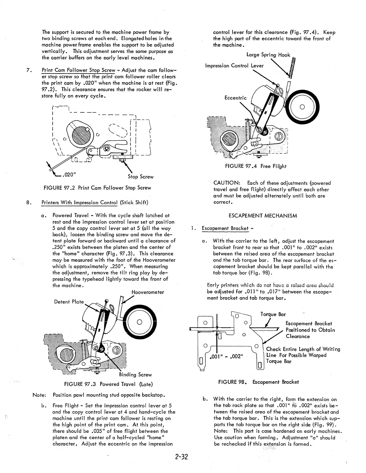
].
Escapement Bracket -
a.
With
the
carrier
to
the
left,
adjust
the
escapement
bracket
front
to
rear
so
that
.00]"
to
.002"
exi sts
between the raised
area
of
the
escapement
bracket
and
the
tab
torque
bar.
The
rear surface
of
the
es-
capement
bracket
should be kept parallel with
the
tab
torque bar (Fi
g.
98).
Early
printers
\Afhich
do
not have a iaised
Oieo
should
be adjusted for
.011"
to,.0]7"
between
the
escape-
ment
bracket
and
tab
torque
bar.
o
o
Escapement Bracket
Positioned
to
Obtain
.
Clearance
o
"r-------~O
Check Entire Length of Writing
Line For Possible Warped
.00111
-
.00211
o Torque
Bar
FIGURE
98.
Escapement Bracket
b.
With
the
carrier
to
the
right,
form
the extension on
the
tab
rack
plate
so
that
.00]"
to
.002"
exists
be-
tween the raised
area
of
the
escapement
bracket
and
the
tab
torque
bar.
This
is
the extension which
sup-
ports
the
tab
torque bar on
the
right
si
de (Fi
g.
99).
Note:
This part
is
case hardened
on
early
machines.
Use
caution when forming. Adjustment
"a"
should
be rechecked
if
this
eX,t,ension
is
formed.