Note:
Check
as follows.
Half-cycle
the
character
and
remove
detent
from
the
head.
Take the play out
of
th-e
head in a clockwise
direction.
Allow
the
detent
to
re-
turn slowly, and observe
the
point
the
detent
strikes or
enters
the
skirt.
Bandwidth equals
the
difference between
the
best and worst
character.
DETENTING
I
1.
\
2.
Print-shaft timing: The
detent
must
enter
and
leave
the
head without hitting
the
skirt.
Check
by manually hal
f-
cycling.
Use a
-5,
home, and a +5
character.
The skirt
clearance
should be
.025"
-
.035"
in a
2-tilt
position. When both dp.tents
are
engaged
fully in
their
respective
notches,
there
should be
.001"
minimum
mo-
tion
of
the
detent-cam
follower with respect
to
the
detent
lever.
THIRD
INSPECTION
PERIOD
)
SELECTION MAGNET UNITS
--
SCOPE
PROCEDURE
,\.
Check
the
pick times
of
all magnets by observing (on an
osci lIoscope)
the
voltage
rise across a 1 O-ohm,
1/2
watt
resistor (part 321271) in series with
the
individual magnet
coi
Is, when a
48-volt
pulse
is
appl ied
to
the
coi
\.
All
pick times must be
ten
milliseconds
Qr
less, with
the
ex-
ception
of
U.C.
shift magnet, red ribbon shift magnet
and
the
keyboard-lock
solenoid. The
U.C.
shift magnet
and red ribbon shift magnet armatures must seal within 12
milliseconds maximum and
the
keyboard lock solenoid
must pick in a maximum
of
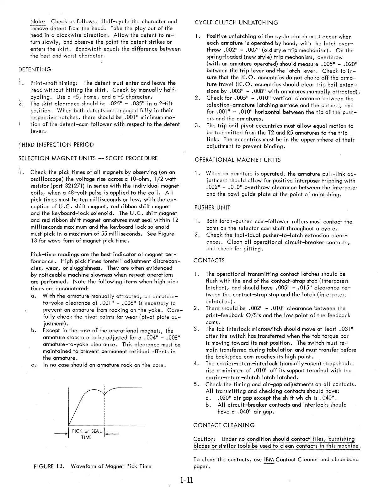
55 milliseconds. See Figure
13 for wave
form
of
magnet pick
time.
Pick-time
readings
are
the
best
indicator
of
magnet
per-
formance. High pick times foretell adjustment
discrepan-
cies,
wear,
or
sluggishness. They
are
often
evidenced
by
noticeable
machine slowness when
repeat
operations
are
performed.
Note
the following items when high pick
times
are
encountered:
a.
With
the
armature manually
attracted,
an
armature-
to-yoke
clearance
of
• 001" - • 006"
is
necessary
to
prevent an armature
from
rocking on
the
yoke.
Care-
fully
check
the
pivot points for Wear (pivot
plate
ad-
justment) •
b.
Except
in
the
case
of
the
operational magnets,
the
armature stops
are
to
be adjusted for a
.004"
- • 008"
armature-to-yoke
clearance.
This
clearance
must be
maintained
to
prevent permanent residual
effects
in
the
armature.
c.
In
no case should an armature rock on
the
core.
I
PICK
or
SEAL
I-
~
TIME
FIGURE
13.
Waveform
of
Magnet Pick Time
1-11
CYCLE
CLUTCH
UNLATCHING
1.
Positive
unlatching
of
the
cycle
clutch
must
occur
when
each
armature
is
operated
by
hand,
with
the
latch
over-
throw
.002"
-
.007"
(old style trip mechanism).
On
the
spring-loaded (new style)
trip
mechanism, overthrow
(with an armature operated) should measure
.005"
-
.020"
between
the
trip
lever
and
the
latch
lever.
Check
to
in-
sure that
the
K.O.
eccentrics
do not choke off
the
arma-
ture travel
(K.O.
eccentrics
should
clear
trip
bail
exten-
sions
by
• 003" - • 008" with armatures manually
attrocted).
2.
Check
for
.005"
-
.010"
vertical
clearance
between
the
selection-armature
latching surface and
the
pushers, and
for
.001"
-
.010"
horizontal between
the
tip
of
the
push-
ers and
the
armatures.
3.
The trip bail pivot
eccentrics
must
allow
equal
motion to
be transmitted
from
the
T2
and
R5
armatures
to
the
trip
link.
The
eccentrics
must be
in
the
upper sphere
of
their
adjustment to prevent
binding.
OPERATIONAL MAGNET UNITS
1.
When an armature
is
operated,
the
armature
pull-link
ad-
justment should
allow
for positive interposer tripping with
.
002" - •
01
A"
overthrow
clearance
between
the
interposer
and the
pawl guide
plate
at
the
point
of
unlatching.
PUSHER
UNIT
1.
Both
latch-pusher
cam-follower rollers must
contact
the
cams
on
the
selector
cam shaft throughout a
cycle.
2.
Check
the individual
pusher-to-Iatch
extension
clear-
ances.
Clean
all operaHonal
circuit-breaker
contacts,
and check for
pitting.
CONTACTS
1.
The operational transmitting
contact
latches
should
be
flush with
the
end
of
the
contact-strap
stop (interposers
latched),
and
should have
.005"
-
.015"
clearance
be-
tween
the
contact-strap
stop and
the
latch
(interposers
unlatched)
•
2.
There shou
Id
be
.002"
- • 010"
clearance
between
the
print-feedback
O/S's
and
the
low point
of
the
feedback
cams.
3.
The
tab
interlock
microswitch should move
at
least
.031"
after
the
switch has transferred when
the
tab
torque bar
is moving toward its rest position. The switch must
re-
main transferred during
tabulation
and must transfer before
the
backspace cam reaches its high
point.
4.
The
carrier-return-interlock
(normally-open) strapshould
rise a minimum
of
.010"
off its support terminal with
the
carrier-return-clutch
latch
latched.
5.
Check
the
timing and
air-gap
adjustments on all
contacts.
All transmitting and
checking
contacts
should have:
a.
.020"
air
gap
except
the
shift which
is
.040".
b.
All
circuit-breaker
contacts
and interlocks should
have a
.040"
air
gap.
CONTACT CLEANING
Caution:
Under no condition should
contact
files,
burnishing
blades
or
similar tools be used to
clean
contacts
in this
machine.
To
clean
the
contacts,
use
IBM
Contact
Cleaner
and
clean
bond
paper.