NOTE: The
operational
clutch
ratchet
must be
posi-
tioned
laterally
on
the
operational shaft
so
that
each
clutch
release
arm will
take
an
equal
lateral
bite on its
respective
clutch
wheel.
This insures
that
neither
clutch
release arm
can
slip sideways off its respe.o.tive
clutch
wheel causing an unwanted cam
operation.
This
condi-
tion is most serious on
the
carrier
return/index
cam as it
will cause an index operation to
occur
each
time
the
cam
is
released.
7.
Clutch Release
Arm
(Fig
.119)-
The lug
at
the bottom
of
each
clutch
release
arm should be formed so
that
it
clears
the interposer lug by
.025"
to
.035"
on
Carrier
Return,
Index and
.035"
to
.045"
on Tab, Backspace, and
Spacebar.
C.R.,
Index
FIGURE
119.
Clutch
Release
Arms
Adjustment
NOTE: The interposers
and
cams must be
latched
when
the
adjustment
is
observed.
Insufficient
clearance
wi
II
cause
the
cams
to
be released
too
early
in
the
rearward travel
of
the
interposers;
con-
sequently
the
operational
latch
involved will not have
sufficient bite on
the
cam follower
lever
as
it
is
operated
down
at
the
rear.
The operational
latch
may slip
from
beneath
the
cam follower and result in an incomplete
operation . Excessive
clearance
could
allow
the
inter-
poser
to
reach
the
limit
of
its travel before the cam
is
released.
NOTE: The
clearance
may be judged with
the
use
of
the
push
end
of
the large spring hook. The
end
of
the
spring hook
is
approximately
.035"
thick.
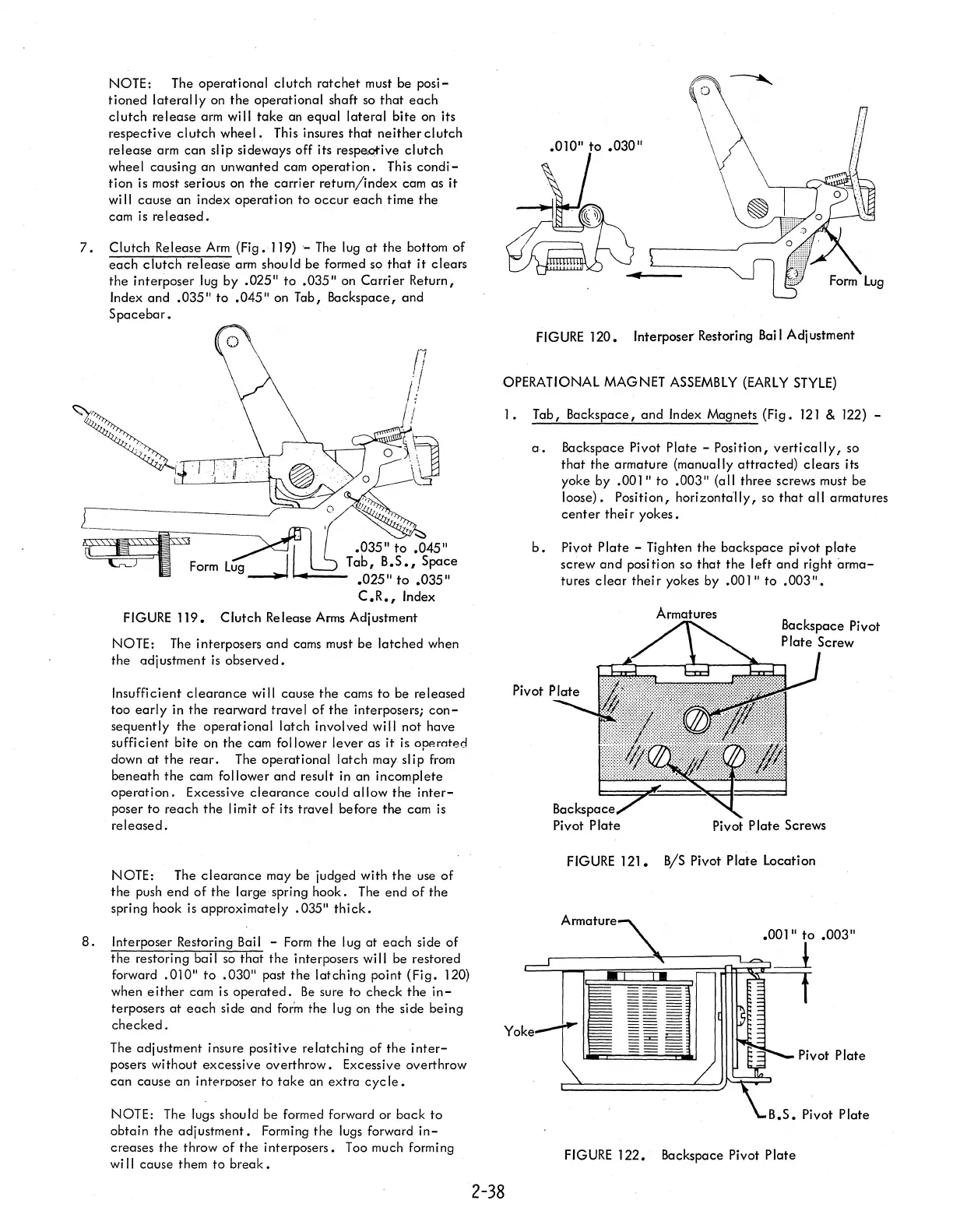
8.
Interposer Restoring Bail -
Form
the lug
at
each
side
of
the
restoring bai I so
that
the
interposers
wi
II
be restored
forward
.010"
to
.030"
past
the
latching
point
(Fig.
120)
when
either
cam is
operated.
Be
sure to
check
the
in-
terposers
at
ea~h
side and
form
the lug on the side being
checked.
The adjustment insure positive relatching
of
the
inter-
posers without excessive overthrow. Excessive overthrow
can
cause an interposer to
take
an
extra
cyc
Ie.
NOTE: The lugs should be formed forward or
back
to
obtain
the
adjustment.
Forming
the
lugs forward
in-
creases
the
throw
of
the
interposers. Too much forming
wi
II
cause them
to
break.
.010"
to
.030"
FIGURE
120.
Interposer Restoring
Bai
I Adjustment
OPERATIONAL MAGNET
ASSEMBLY
(EARLY
STYLE)
2-38
1.
Tab, Backspace,
and
Index Magnets
(Fig.
121
& 122) -
a.
Backspace Pivot Plate - Position,
vertically,
so
that
the
armature {manually attracted}
clears
its
yoke by
.001"
to
.003"
{a
II
three screws must be
loose}. Position,
horizonta"ily, so
that
all
armatures
center
thei r
yokes.
b.
Pivot
Plate
- Tighten
the
backspace pivot
plate
screw
and
position so
that
the
left
and
right
arma-
tures
clear
their
yokes by
.001"
to
.003".
Pivot P
late
Screws
FIGURE
121.
B/S Pivot Plate Location
Armature
FIGURE
122.
Backspace Pivot
Plate

 Loading...


