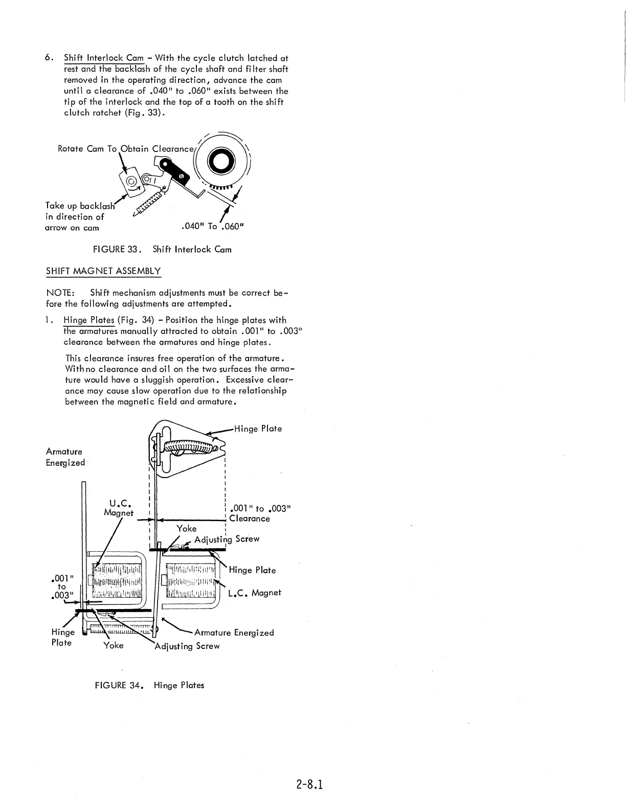
6.
Shift Interlock
Cam
- With
the
cycle
clutch latched
at
rest and the backlash
of
the
cycle
shaft and fi Iter shaft
removed
in
the operating
direction,
advance
the
cam
until a
clearance
of
.040"
to
.060"
exists between the
tip
of the interlock and the top of a tooth
on
the shift
clutch
ratchet (Fig.
33).
Take up backlash
in
direction
of
arrow on cam
FIGURE
33.
Shift Interlock
Cam
SHIFT
MAGNET
ASSEMBLY
NOTE: Shift mechanism adjustments must be correct
be-
fore the following adjustments
are
attempted.
1. Hinge Plates (Fig. 34) - Position the hinge plates with
the armatures manually
attracted
to obtain
.001"
to
.003"
clearance
between
the
armatures and hinge
plates.
This
clearance
insures free operation of the armature.
With no
clearance
and
oil
on
the two surfaces the
arma-
ture would have a sluggish
operation.
Excessive
clear-
ance
may cause slow operation due to the relationship
between the magnetic field and armature.
Armature
Energized
.001"
to
I
I
I
Hinge Plate
:
.001"
to
.003"
-""i~
_____
----I.
Clearance
Yoke
~
Adjusti~g
Screw
iIT=1...:===~
1'~~~1
"!!%1:'dP(!llt'li Hinge Plate
Hltll\tll!tli'lilli'l
.00~3)"
~~~~~~
L.C.
Magnet
"-Armature
Energized
Adjusting
Screw
FIGURE
34.
Hinge Plates
2-8.1