2.
I Shift
Clutch
Ratchet Adjustment (Late) (Fig.
29.1)
-
Ad-
just
the
shift
clutch
ratchet
to satisfy
the
following
con-
dition.
With
the
machine turned
off
and
the
shift cam
detented,
the shift
clutch
ratchet
will
rotate
.028"
to
.050"
when the shift
release
arm releases
the
ratchet.
The rotation
can
be observed
relative
to
the
shift
re-
lease
arm
and
the shift cam stop.
Be
sure to loosen the
set
screw in the
ratchet
before
adjusting.
Remove play
from
the
shift
ratchet
in a clockwise
direction.
Note:
The
C-7
cam must be removed to make the
above
adjust-
ment.
•
028"
to
.050"
FIGURE
29.
I Shift
Clutch
Ratchet Adjustment
The adjustment
of
the
shift
clutch
ratchet
determines
how much the
clutch
spring will be expanded when the
shift mechanism
is
at
rest.
Expanding the spring too
much may
cause
failure
of
the cam to
reach
the
detent-
ed
position, because the spring would be expanded too
soon.
Insufficient expansion would allow the
clutch
spring to drag when
at
rest
creating
a load on
the
motor
and
on
the
shift
release
mechanism.
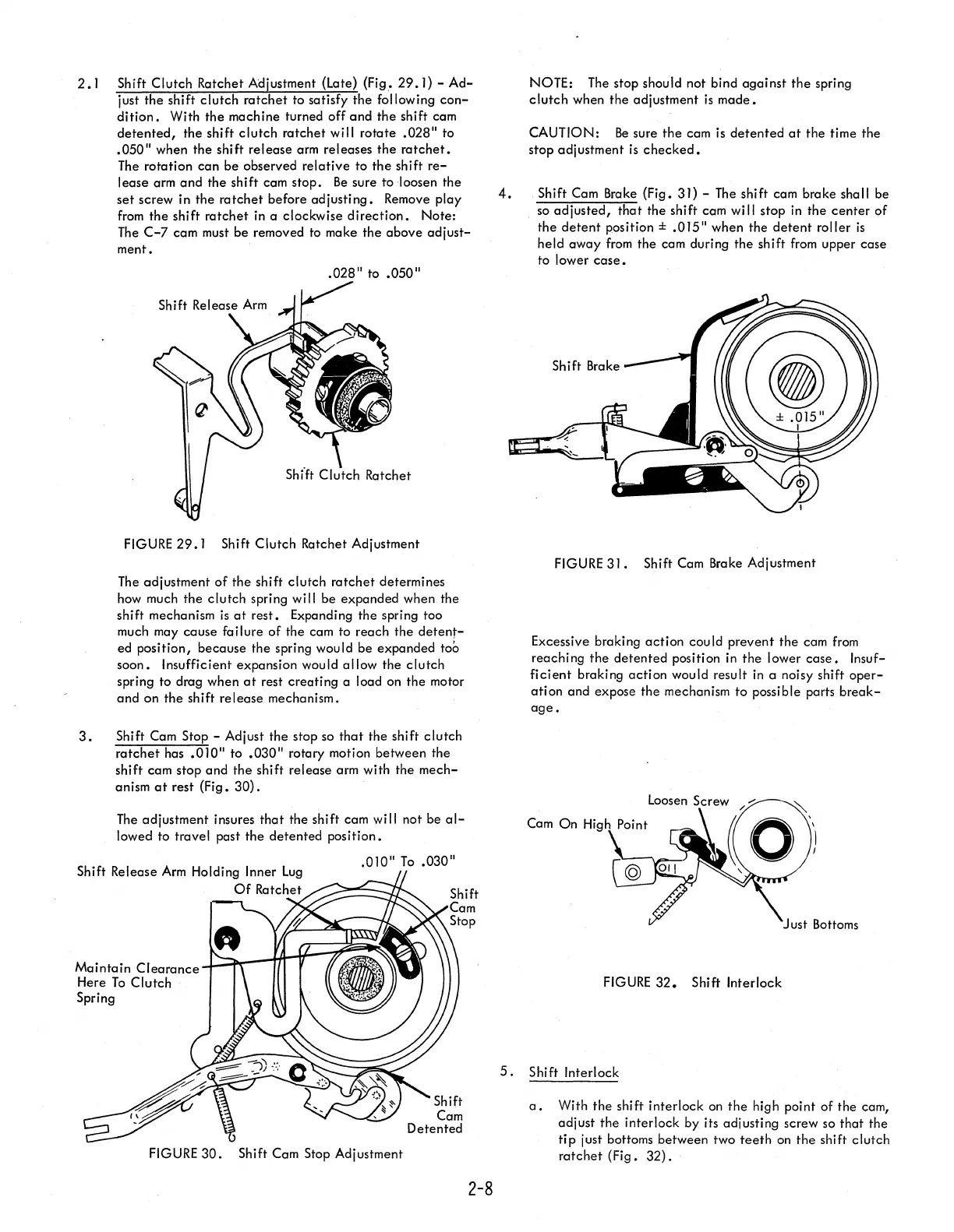
3.
Shift Cam Stop - Adjust the stop so
that
the shift
clutch
ratchet
has
.010"
to
.030"
rotary motion between the
shift cam stop and
the
shift release arm with the
mech-
anism
at
rest (Fig.
30).
The
adjustment insures
that
the shift cam will not be
al-
lowed to travel past the
detented
position •
Shift
Release
Arm
Holding Inner
Lug
Of
Ratchet
Maintain
Clearance
•
010"
To
.030"
4.
NOTE: The stop should not bind
against
the
spring
clutch
when
the
adjustment
is
made.
CAUTION:
Be
sure
the
cam is
detented
at
the
time the
stop adjustment
is
checked.
Shift Cam Brake (Fig. 31) - The shift cam brake shall be
so
adjusted,
that
the shift cam
wi
II
stop in
the
center
of
the
detent
position ±
.015"
when the
detent
roller
is
held
away
from
the cam during the shift
from
upper case
to lower
case
•
FIGURE
31
• Shift Cam Brake Adjustment
Excessive braking
action
cou
Id
prevent
the
cam
from
reaching
the
detented
position
in
the
lower
case.
Insuf-
ficient
braking
action
would result in a noisy shift
oper-
ation
and expose
the
mechanism
to
possible parts
break-
age.
Here
To
Clutch
FIGURE
32.
Shift Interlock
Spring
FIGURE
30.
Shift Cam Stop Adjustment
2-8
5.
Shift Interlock
a.
With
the
shift interlock
on
the
high point of the cam,
adjust
the
interlock by its adiusting screw so
that
the
tip
just bottoms between two
teeth
on
the
shift
clutch
ratchet
(Fig.
32).