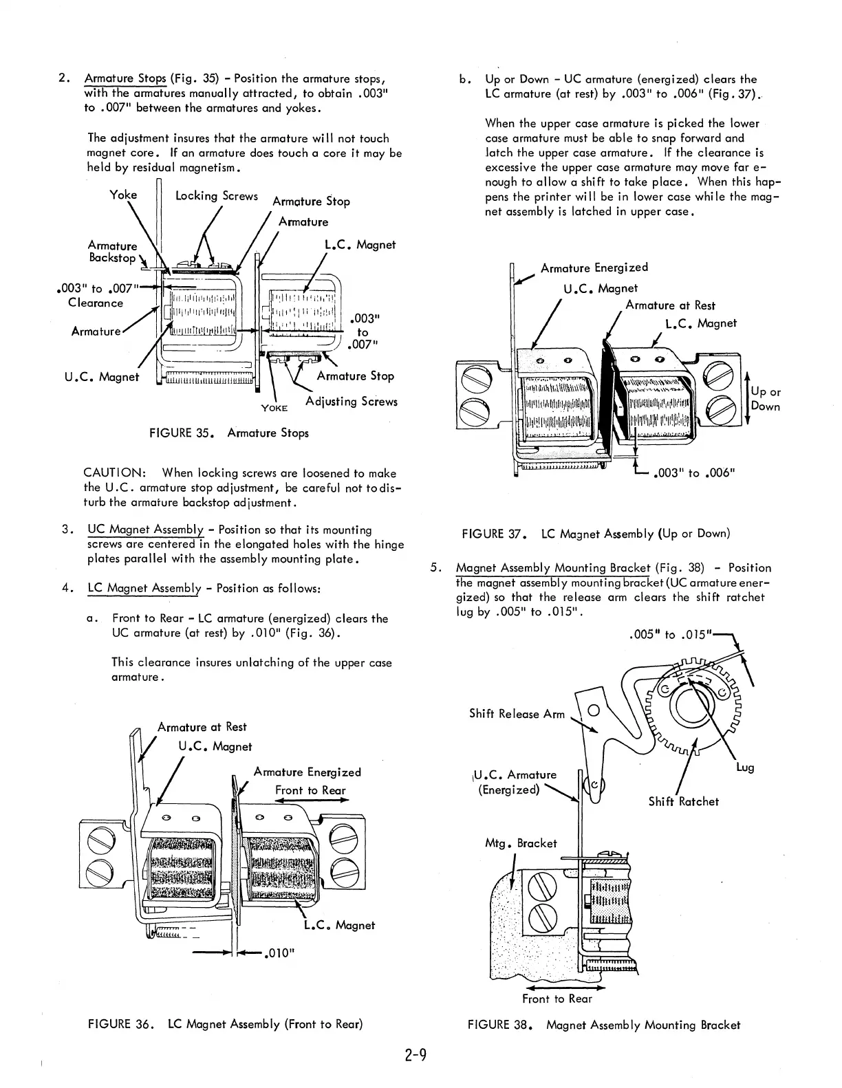
2.
Armature Stops (Fig.
35)
- Position
the
armature stops,
with
the
armatures manually
attracted,
to
obtain .003"
to
.007" between
the
armatures and
yokes.
The
adjustment insures
that
the
armature will not touch
magnet
core.
If
an armature does touch a core
it
may be
held by residual magnetism.
Yoke
~
locking
Screws "
Armoture Stop
Armature
Backstop
~~"~~='iI
FIGURE
35. Armature Stops
CAUTION: When locking screws
are
loosened
to
make
the
U.C.
armature stop adjustment, be careful not
todis-
turb
the
armature backstop adjustment.
3.
UC
Magnet Assembly - Position so
that
its mounting
screws
are
centered
in the
elongated
holes with
the
hinge
plates
parallel
with the assembly mounting
plate.
4.
LC
Magnet Assembly - Position as follows:
a.
Front to Rear -
LC
armature (energized)
clears
the
UC
armature (at rest) by
.010"
(Fig.
36).
This
clearance
insures unlatching
of
the
upper case
armature.
Armature Energized
FIGURE
36.
LC
Magnet Assembly (Front
to
Rear)
2-9
b.
Up
or
Down
-
UC
armature (energized)
clears
the
LC
armature (at rest) by .003"
to
.006" (Fig. 37)."
When
the
upper case armature is
picked
the lower
case armature must be
able
to
snap forward and
latch
the
upper case
armature.
If
the
clearance
is
excessive
the
upper case armature may move far
e-
nough
to
allow
a shift
to
take
place.
When this
hap-
pens
the
printer
wi
II
be in lower
case
whi Ie
the
mag-
net
assembly
is
latched in upper
case.
Armature Energized
U.C.
Magnet
Armature
at
Rest
.003"
to
.006"
FIGURE
37.
LC
Magnet Assembly (Up or
Down)
5.
Magnet Assembly Mounting Bracket
(Fig.
38) - Position
the
magnet assembl y mounting
bracket
(UC armature
ener-
gized)
so
that
the
release arm
clears
the
shift
ratchet
lug by .005"
to
.015".
Shift Release
Arm
\U.C.
Armature
(Energized)
Mtg.
Bracket
FIGURE
38.
Magnet Assembly Mounting Bracket