7.
Pawl
Clearance
(Fig. 165) -
The
upright lug of the
tab
latch should be formed forward or back
so
that
the tip
of
the escapement pawl clears the escapement rack
teeth by
.005"
-
.010"
when the
tab
lever
is
latched
to the
rear.
Small Screwdriver
Escapement Bracket
FIGURE
165.
Pawl
Clearance
Adjustment
8.
Carrier Return
Tab
Interlock (Fig. 166) - With the
car-
rier return clutch latch (in a carrier return operation)
the upright lug
of
th~
tab latch should
clear
the end
of
the tab lever pawl by
.005"
-
.025".
The rear lug
of
the
tab
latch should
be
formed forward .
.or
back
to
ob-
tain this condition.
NOTE: After this adjustment
is
made, the
carrier
re-
turn mechanism should be unlatched and a
tab
lever
latched
out.
The
rear
lug on the
tab
latch should
again
be checked to ensure
that
it
is
not touching
the escapement torque
bar.
Torque
Bar
Tab
Lever7lf.005"
To
.025"
~
....
~""
~~'~
\ I
'''')
-
....
/
I Escapement
Bar
FIGURE
166.
Interlock
9.
Tab
Trigger Extension (Fig. 167) -
Form
the front
(curved) lug
of
the
tab
trigger to-obtain
.016"
-
.023"
clearance
between this lug and the
tab
torque bar with
JlII
parts
at
rest.
FIGURE
167. Tab Trigger Extension
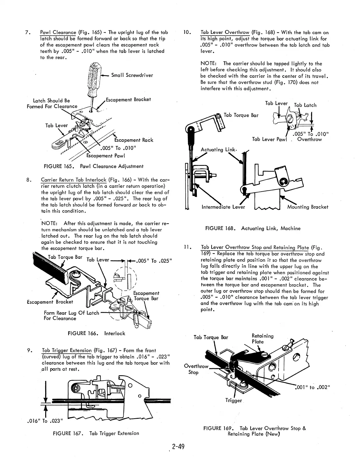
10.
II.
2-49
Tab
Lever Overthrow (Fig. 168) - With the tab cam on
its high point, adjust the torque bar
actuating
link for
.005"
-
.010"
overthrow between the tab latch and
tab
lever.
NOTE:
The
carrier
should be tapped lightly to the
left before checking this adjustment.
It
should also
be checked with the
carrier
in
the
center
of
its
travel.
Be
sure
that
the overthrow stud (Fig. 170) does not
interfere with this adjustment.
Tab Torque
Bar
FIGURE
168. Actuating Link, Machine
Tab Lever Overthrow
Stop and Retaining Plate (Fig.
169) - Replace the
tab
torque bar overthrow stop
and
retaining
plate
ond position it so
that
the overthrow
lug falls
directly
in line with the upper lug on the
tab trigger and retaining
plate
when positioned
against
the torque bar maintains
.001"
-
.002"
clearance
be-
tween the torque bar and escapement
bracket.
The
outer lug
or
overthrow stop should then be formed for
.005"
-
.010"
clearance
between the tab lever trigger
and the overthrow
lug with the tab
canion
its high
point.
Trigger
FIGURE
169.
Tab Lever Overthrow Stop &
Retaining Plate (New)