Since this .260" to .270"
is
measured between
the
typehead
and the platen it
is
not a measurement of
the
powered travel
of
the
typehead.
The
.020" to
.030" free flight
is
included in this .260"
to
.270"
and must
be
subtracted in order
to
determine the
amount of powered
travel.
The
powered travel must
never
exceed
.265" as this will
cause
typehead
breakage.
The base of
the
Hooverometer handle can be used
as a measuring devi
ce
as illustrated in Fig.
95.
The
handle base
is
about .250" thick; however
they
do
not
all
measure the
same.
Each handle should be
measured with"a dial
indicator
or micrometer to
de-
termine its
exact
size.
When the
size
of the handle
base
is
determined,
a thickness of
tab
cards should
be
placed
around
the
platen
that will total .260"
to
.270" when added
to
the thickness of
the
handle
base.
e.
Both adjustments must be rechecked
and
refined
un-
ti I these conditions
are
obtained.
Be
sure
to
tighten
both screws firmly when
the
adjustments
are
com-
pleted.
NOTE:
The
adjustments should be checked with
the
ri
bbon removed.
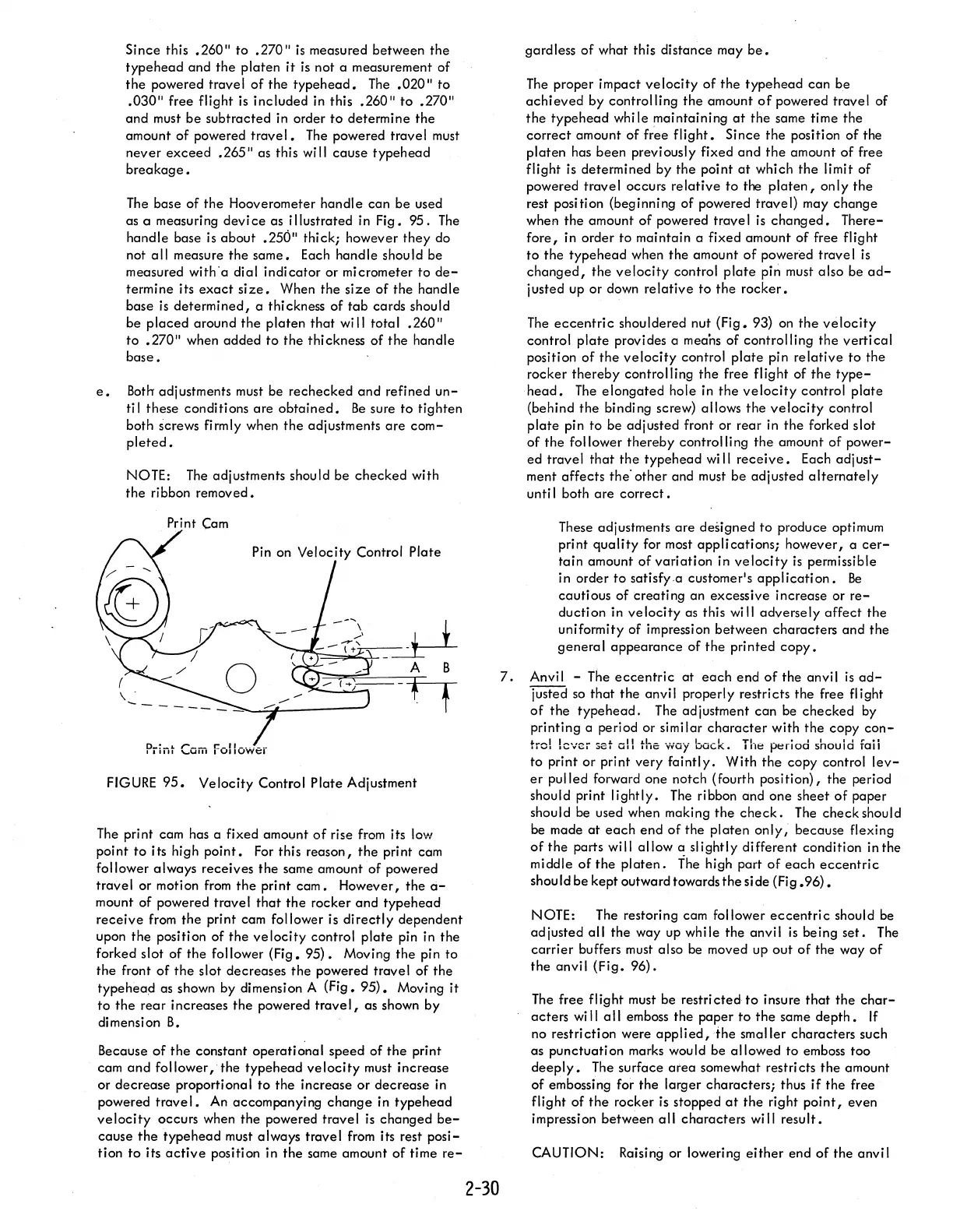
Print
Cam
Piint
Com
follower
FIGURE
95.
Velocity Control Plate Adjustment
The
print cam has a fixed amount
of
rise
from
its low
point to its high
point.
For
this reason,
the
print cam
follower always receives the same amount of powered
travel or motion
from
the
print
cam.
However, the
a-
mount of powered travel
that
the
rocker
and
typehead
receive
from
the
print cam follower is
directly
dependent
upon the position of the
velocity
control
plate
pin in the
forked slot of the follower (Fig.
95).
Moving the pin to
the
front
of
the
slot decreases
the
powered travel of the
type
head as shown by dimension A (Fig.
95).
Moving
it
to
the
rear increases
the
powered trave
I,
as shown by
di
mensi on
B.
Because
of
the
constant operational speed of
the
print
cam
and
follower, the typehead
velocity
must increase
or
decrease
proportional to
the
increase
or
decrease in
powered
travel.
An
accompanying
change
in typehead
velocity
occurs when the powered travel
is
changed
be-
cause
the
type head must always trave I
from
its rest
posi-
tion
to
its
active
position in
the
same amount of time
re-
2-30
gardless of what this distance may
be.
The
proper impact
velocity
of
the
typehead
can be
achieved
by controlling
the
amount
of
powered travel of
the
typehead
while maintaining
at
the same time the
correct
amount of free
flight.
Since the position of the
platen
has been previously fixed
and
the
amount
of
free
flight
is
determined
by
the
point
at
which
the
limit of
powered travel occurs
relative
to the
platen,
on
Iy
the
rest position (beginning of powered travel) may change
wheA
the amount of powered trave I
is
changed.
There-
fore,
in order to maintain a fixed amount of free flight
to
the type head when the amount
of
powered travel
is
changed,
the
velocity
control
plate
pin must also be
ad-
justed up or down
relative
to
the
rocker.
The
eccentric
shouldered nut (Fig. 93)
on
the
velocity
control
plate
provides a means of controlling
the
vertical
position of
the
velocity
control
plate
pin
relative
to
the
rocker thereby
controlling
the
free flight of
the
type-
head.
The
elongated
hole in
the
velocity
control
plate
(behind
the
binding screw) allows
the
velocity
control
plate
pin to be adjusted front or rear in
the
forked slot
of the
follower thereby controlling
the
amount of power-
ed travel
that
the
typehead
wi
II
receive.
Each adj
ust-
ment affects the· other and must
be
adjusted
alternately
unti I both
are
correct.
These adjustments
are
designed to produce optimum
pri nt qua
Ii
ty
for
most
app
Ii cati ons; however, a
cer-
tain amount
of
variation in
velocity
is
permissible
in order
to
satisfy"a customer's
application.
Be
cautious of creating an excessive increase or
re-
duction in
velocity
as this will adversely
affect
the
uniformity of impression between characters and
the
genera I
appearance
of
the
printed
copy.
7.
Anvil - The
eccentric
at
each
end
of
the anvil
is
ad-
justed
so
that the anvil properly restricts the free flight
of
the
typehead.
The
adjustment can be checked by
printing a period or similar
character
with
the
copy
con-
trel
lever
set
all
the way
back.
The
period shouid
raii
to print or print very
faintly.
With
the
copy control
lev-
er
pulled forward one notch (fourth position), the period
should print
lightly.
The
ribbon and one sheet of paper
should be used when making
the
check.
The
check should
be made
at
each
end
of
the platen
only;
because flexing
of
the
parts will allow a slightly different condition
inthe
middle
of
the
platen.
The
high part
of
each
eccentric
should be kept outward towards
the
side (Fig
.96).
NOTE:
The
restoring cam follower
eccentric
should be
adjusted
all
the way up while the anvil
is
being
set.
The
carrier
buffers must also be moved up
out
of
the way
of
the anvil (Fig.
96).
The
free flight must be
restricted
to
insure
that
the
char-
acters
wi
II
a
II
emboss the paper
to
the
same
depth.
If
no restriction were
applied,
the
smaller characters such
as punctuation marks would be allowed to emboss too
deeply.
The surface
area
somewhat restri cts
the
amount
of embossing for the larger characters; thus
if
the free
flight of
the
rocker is stopped
at
the
right
point,
even
impression between
all
characters will result.
CAUTION: Raising or lowering
either
end
of
the anvil