b.
Carrier
Shoe (late) - Adjust
the
upper
carrier
shoe
eccentric
mounting stud
to
provide .002"
to
.006"
vertical
motion
of
the
carrier
at
the
rear (Fig. 92)
when the spring load on the upper shoe is suppressed.
CAUTION:
FIGURE
92.
Carrier Shoe - New Style
Eccentric
Stud
Lock-Nut
NOTE:
The
vertical
motion may be
felt
by firmly
moving the
carrier
up and down
at
the
rear,
so as
to
overcome the effects
of
the
spring load
on
the upper
shoe.
6.
Velocity
Control Plate - The
velocity
control
plate
must
be
adjusted
to
satisfy the following two conditions:
a.
With
the
cam follower held lightly against the low
point of the print
cam,
the
center
of the home
char-
acter
should
clear
the
platen
by .260"
to
.270".
b.
With
the
cam follower held lightly against the high
point
of
the
print
cam,
the
home
character
should
clear
the
platen by .020" to
.030".
The
copy control lever should be forward
f~r
both
ad-
justments. These adjustments shou
Id
be made with
the
carrier
at
the
extreme left hand position.
The adjustments
can
be made easily
if
the
following
pro-
cedure
is
used.
a.
Raise the anvil adjusting
eccentrics
and the restor-
ing cam follower
eccentric
to
prevent nny
inter-
ference,
and remove
the
ribbon feed
plate
for
ac-
cessibility.
(Fig. 96).
b.
If
the
velocity
control
plate
is
loose or completely
out of adjustment,
set
the
high part of
the
eccentric
forward and tighten
it
in
place.
Adjust
the
plate
so
that
about
1/32" of
the
adjusting slot
is
visible
a-
bove
the
binding screw and tighten
the
screw friction
tight.
These settings provi de a good starting
point.
(Fig.
93).
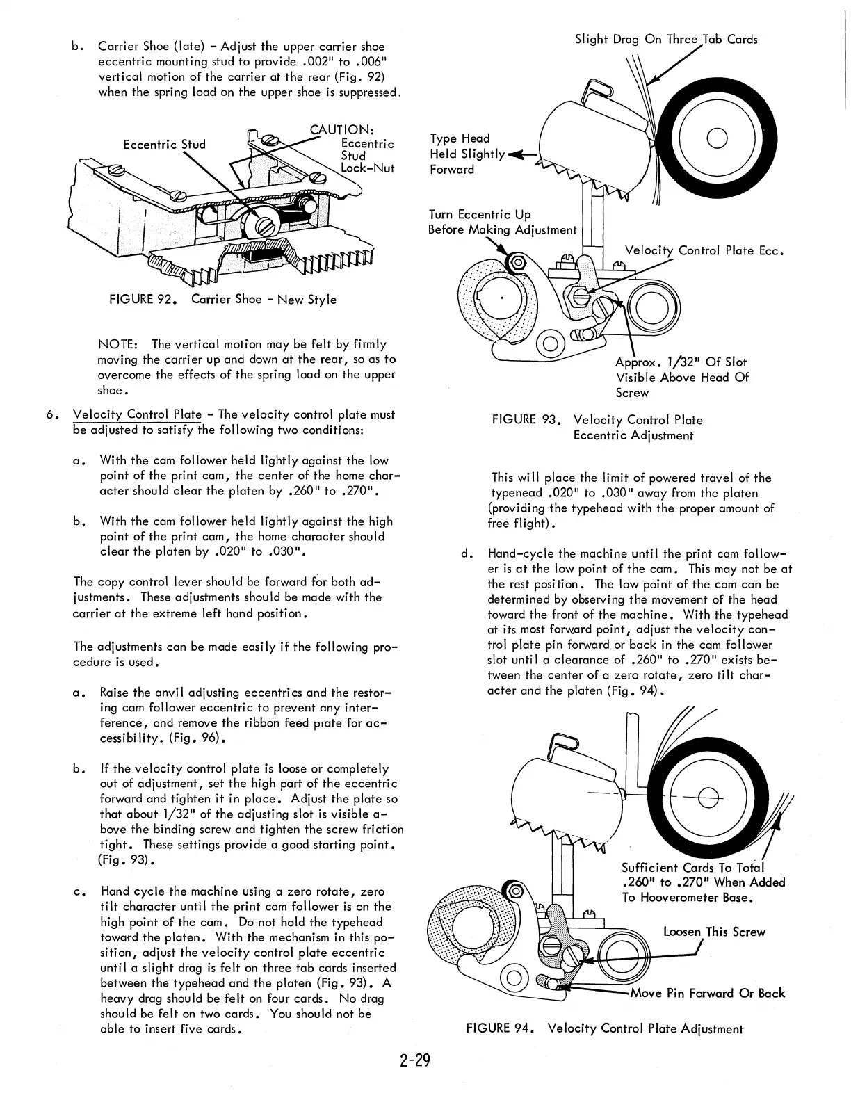
c.
Hand
cycle
the machine using a zero
rotate,
zero
tilt
character
until
the
print cam follower
is
on
the
high point of the
cam.
Do
not hold
the
typehead
toward the
platen.
With the mechanism in this
po-
sition,
adjust
the
velocity
control
plate
eccentric
until a slight drag
is
felt
on
three
tab
cards inserted
between the typehead and
the
platen (Fig.
93).
A
heavy drag should be
felt
on
four
cards.
No
drag
should be
felt
on
two
cards.
You
should not be
able
to
insert five
cards.
2-29
Type Head
Held
Slightly
Forward
Screw
Control
Plate Ecc.
FIGURE
93.
Velocity
Control Plate
Eccentric Adjustment
This
will
place
the limit of powered travel of the
typenead .020"
to
.030"
away
from
the platen
(providing
the
typehead with
the
proper amount of
free
flight).
d.
Hand-cycle the machine until
the
print cam
follow-
er
is
at
the
low point
of
the
cam.
This
may not be
at
the rest position.
The
low point of the cam
can
be
determined by observing
the
movement of the head
toward
the
front of
the
machine.
With
the
type head
at
its most forward
point,
adjust
the
velocity
con-
trol
plate
pin forward or
back
in the cam follower
slot until a
clearance
of .260"
to
.270" exists
be-
tween the
center
of a
zero
rotate,
zero
tilt
char-
acter
and
the
platen
(Fig.
94).
-_-J
=:::==:::::::~AO\,e
Pin Forward
Or
Back
FIGURE
94.
Velocity
Control Plate Adjustment