If
the
bracket
were adjusted too low, the steps
woll
Id
be
at
an
angle
to
the
line
of
motion
of
the
cycle
clutch
latch.
The
latch
would have difficulty in moving
for-
ward
to
release the
clutch
sleeve,
and
a slow, hesitant
operation would
result.
With
the
bracket
too
high,
the
force
of
stopping
the
cycle
shaft through
the
cycle
clutch
sleeve would
tend
to cam
the
latch
forward. A
repeat
cyc
Ie
operati
on
could
result.
When properly adjusted the
top
of
the
latch pivot pin is
1.546"
below
the
top
of
the
print
shaft.
This
distance
can be measured
wi
th
the
use
of
the
Hooverometer.
Wi
th
the
head
of
the
Hooverometer
set
at
the
#3
scribe
line,
the head should rest
on
top
of
the
print shaft with
tl-e
handle touching
the
latch pivot pin (Fig.
41).
Be
sure
the
Hooverometer handle is
vertical.
It
will be
vertical
if
the
base
of
the
handle
is
centered
over
the
latch pivot
pin.
NOTE: Changing
the
height
of
the
cycle
clutch
latch
necessitates a readjustment
of
the
cycle
clutch
collar,
cycle
clutch
stop,
and
the
cycle
clutch latch restoring
mechanism.
CA.UTION:
The
latch
bracket
must not become cocked
so
that
only a corner
of
the
latch
plate
is
stopping
the
sleeve.
Excessive
wear
could
result.
The
cycle
clutch
sleeve
could also be
tilted
by
the
latch causing
it
to
bear
against
the
cycle
clutch
pulley hub creating a
noisy
operation.
3.
Cycle
Clutch Spring and
Collar
Adjustments (Early)
a., Lateral position
of
the
spring - Loosen
the
collar
and position
the
spring left or right
on
its hubs so
that
the
right hand end
of
the spring
wi
II
clear
the
face
of
the
cycle
clutch
pulley by
.004"
to
.012"
(F.ig.
42).
NOTE:
This
adjustment insures
that
a maximum
number
of
coils
of
the
spring clutch
wi
II
grip
the
driving hub during a
cycle
operation.
Any
slip-
page between
the
driving hub and
the
spring
clutch
could
decrease
the
typehead
velocity
during a
print operation resulting in intermittent
light
im-
pression. A
lack
of
clearance
between
the
right
end
of
the
spring
clutch
and
the
face
of
the
cycle
clutch
Sleeve
Collar Adjustment
Pulley
Cycle
Clutch Spring
Sleeve
End
Play
FIGURE
42.
Lateral Position
of
the
Cycle
Clutch
Spring
and
Collar
pulley
would
create
a bind causing
the
spring
clutch
to place a heavy torque on the
cycle
clutch
sleeve.
This excessive torque on the sleeve results in a
sluggish
operation
because
the
cycle
clutch
latch
trip
lever
has difficulty tripping
the
latch
off
the
sleeve.
b.
Lateral position
of
the
collar
- position
the
collar
left or right so
that
the
sleeve
will have
.010"
to
.015"
end
play.
NOTE:
This
adjustment insures
that
there will be
no
binds between
the
right end
of
the
sleeve
and
the
cycle
clutch
pulley.
A bind will cause a sluggish
operation just
as
in
the
previous adjustment.
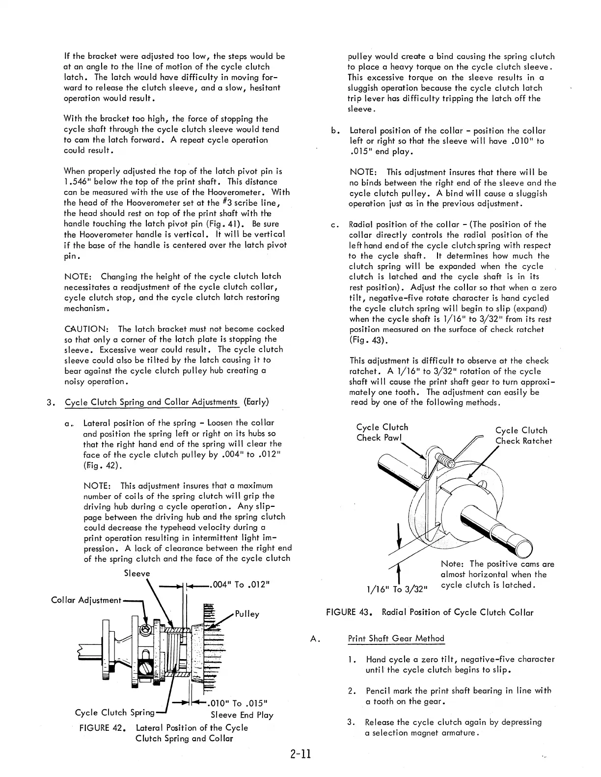
c.
Radial position
of
the
collar
- (The position
of
the
collar
directly
controls
the
radial position
of
the
left hand end
of
the
cycle
clutch spring with respect
to
the
cycle
shaft.
It
determines how much the
clutch spring
wi
II
be expanded when
the
cycle
clutch is
latched
and
the
cycle
shaft
is
in its
rest position). Adjust
the
collar
so
that
when a
zero
ti
It,
negative-five
rotate
character
is
hand
cycled
the
cycle
clutch
spring will begin
to
slip (expand)
when
the
cycle
shaft is
1/16"
to
3/32"
from
its rest
position measured on
the
surface
of
check
ratchet
(Fig. 43).
This
adjustment
is
difficult
to
observe
at
the
check
ratchet.
A
1/16"
to
3/32"
rotation
of
the
cycle
shaft
wi
II
cause
the
print shaft
gear
to
turn
approxi-
matey
one
tooth.
The
adjustment
can
easi ly be
read
by
one
of
the foil owi
ng
methods.
Cycle
Clutch
Check
Ratchet
Note:
The positive cams
are
almost horizontal when
the
1/16"
To
3/32"
cycle
cl utch
is
latched.
FIGURE
43.
Radial Position
of
Cycle
Clutch
Collar
A.
Pri
nt Shaft
Gear
Method
1. Hand
cycle
a
zero
ti
It,
negative-five
character
until
the
cycle
clutch
begins to
slip.
2.
Pencil mark
the
print shaft bearing in line with
a tooth on
the
gear.
3.
Release
the
cycle
clutch
again
by
depressing
a
selection
magnet armature.
2-11