4.
Slowly hand
cycle
the
machine until
the
check
pawl just drops into a tooth on the
check
rat-
chet.
The print shaft gear should have
rotated
1/2
to one
tooth.
If the print shaft
gear
rotat-
ed
further than one tooth
the
collar
must be
moved top toward
the
rear.
Less
than
1/2
to
one
tooth,
move
it
top
toward
the
front.
A
zero
ti
It,
negative-f
ive rotate
character
is used
because
it
offers
the
greatest
resistance to
the
cycle
shaft during
the
restoring portion
of
a
cycle,
caus-
ing
the
cycle
clutch
spring to slip
at
the
earliest
possible
time.
.
NOTE:
If
the
collar
shouid become completely
loose, a good starting point may be obtained by
positioning
the
collar
so
that
its adjusting screw head
is
approximately in line with the high point
of
the
negative-five
cam.
CAUTION:
The
cycle
clutch stop
attached
to
the
collar
may prevent
the
shaft
from
reaching
the
latched
position.
Any change in the
cycle
clutch
collar
adjustment
wi
II
necessitate a readjustment
of
the stop; the refore
it
is
usually best to loosen
the
stop before attempti
ng
to
adjust the
collar.
B.
Degree Wheel Method
With the machine
at
zero
degrees
(cycle
clutch
latched
at
rest)
select,a
-5
rotate,
0
tilt
character
and hand
cycle
the
machine slowly. The
cycle
clutch
spring should slip and stop driving
at
170
to
175
degrees.
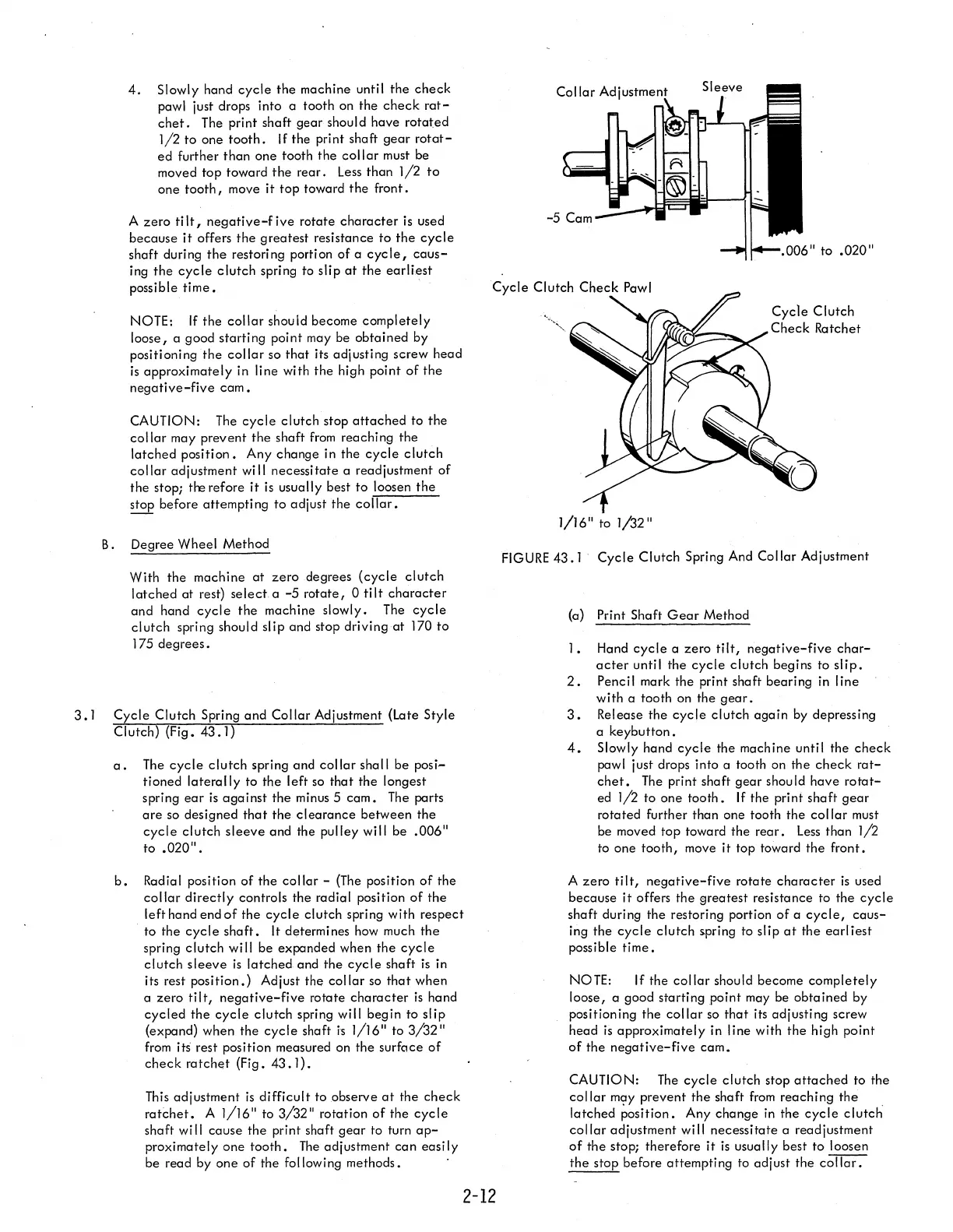
3.1
Cycle
Clutch Spring
and
Collar
Adjustment (Late Style
Clutch) (Fig.
43.1)
a.
The
cycle
clutch
spring and
collar
shall be posi-
tioned
laterally
to the left
so
that
the longest
spring
ear
is
against
the minus 5
cam.
The perts
are
so designed
that
the
clearance
between the
cycle
clutch
sleeve
and the pulley will be .006"
to
.020".
b.
Radial position
of
the
collar
-
(The
position
of
the
collar
directly
controls the radial position
of
the
left hand end
of
the
cycle
clutch spring with respect
to the
cycle
shaft.
It determines
how
much
the
spring clutch wi
II
be expanded when
the
cycle
clutch
sleeve
is
latched
and
the
cycle
shaft
is
in
its rest position.) Adjust the
collar
so
that
when
a
zero
tilt,
negative-five
rotate
character
is
hand
cycled
the
cycle
clutch spring will begin to
slip
(expend) when the
cyc
I e shaft
i'S
1/16" to
3/32"
from
its rest position measured on the surface
of
check
ratchet
(Fig.
43.1).
This
adjustment
is
difficult
to observe
at
the
check
ratchet.
A 1/16" to 3/32" rotation
of
the
cycle
shaft
wi
II
cause the print shaft
gear
to turn
ap-
proximately one
tooth.
The
adjustment
can
easi
Iy
be read by one
of
the following methods.
2-12
1/16" to 1
/32
"
Cycle
Clutch
Check
Ratchet
FIGURE
43.1
Cycle
Clutch Spring And Collar Adjustment
(a) Print Shaft
Gear
Method
1. Hand
cycle
a
zero
tilt,
negative-five
char-
acter
until the
cycle
clutch begins to
slip.
2.
Pencil mark the print shaft bearing in line
with a tooth on the
gear.
3.
Release the
cycle
clutch
again
by depressing
a keybutton.
4.
Slowly hand
cycle
the machine until the
check
pewl just drops into a tooth on the
check
rat-
chet.
The
print shaft
gear
should have
rotat-
ed 1/2 to one
tooth.
If
the print shaft
gear
rotated further than one tooth the
collar
must
be moved top toward the
rear.
Less
than 1/2
to one
tooth,
move
it
top toward
the
front.
A
zero
ti It,
negative-five
rotate
character
is
used
because
it
offers the
greatest
resistance to the
cycle
shaft during the restoring portion
of
a
cycle,
caus-
ing the
cycle
clutch
spring to slip
at
the earl iest
possible
time.
NOTE: If the
collar
should become
completely
loose, a good starting
point
may be
obtained
by
positioning the
collar
so
that
its adjusting screw
head
is
approximately in line with
the
high point
of
the
negative-five
cam.
CAUTION:
The
cycle
clutch stop
attached
to the
collar
m9Y
prevent
the
shaft
from
reaching
the
.
latched position. Any change
in
the
cycle
clutch
collar
adjustment
wi
II
necessitate a readjustment
of
the
stop; therefore
it
is
usually best to loosen
the
stop before attempting to adjust the
collar.