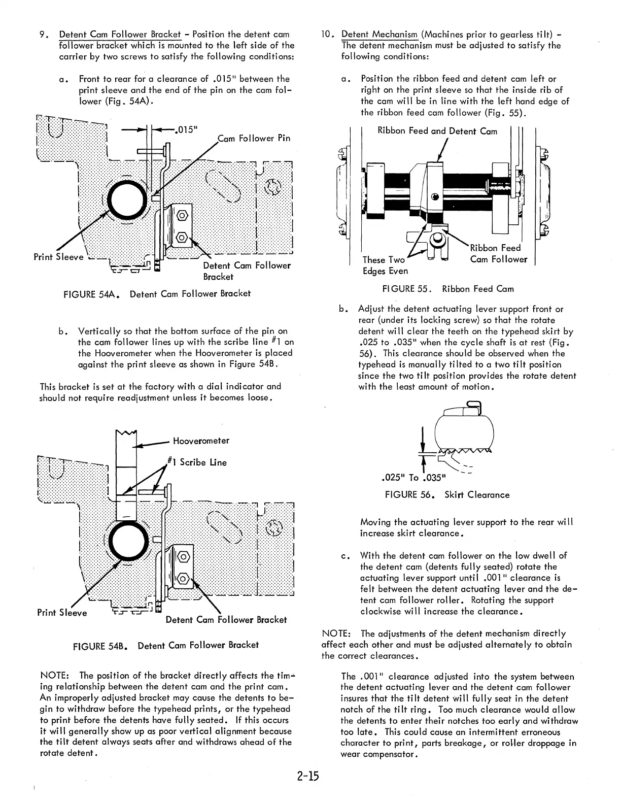
9.
Detent
Cam
Follower Bracket - Position
the
detent
cam
follower bracket which
is
mounted
to
the left side of the
carrier
by two screws
to
satisfy the following conditions:
a.
Front
to
rear for a
clearance
of
.015"
between the
print sleeve and the end of the pin
on
the cam
fol-
lower (Fig.
54A).
Cern
Follower
Pin
Detent
Cam
Follower
Bracket
FIGURE
54A.
Detent
Cam
Follower Bracket
b.
Vertically
so
that
the bottom surface of
the
pin on
the cam follower lines up with the scribe line
#1
on
the Hooverometer when the Hooverometer
is
placed
against
the
print sleeve as shown in Figure 54B.
This
bracket is
set
at
the factory with a dial indicator and
should not require readjustment unless
it
becomes loose.
c...._-
Hooverometer
Detent
Cam
Follower Bracket
FIGURE
54B. Detent
Cam
Follower Bracket
NOTE:
The
position
of
the bracket
directly
affects
the
tim-
ing relationship between the
detent
cam and the print
cam.
An
improperly adjusted bracket may cause the detents
to
be-
gin
to
withdraw before the typehead prints,
or
the
typehead
to
print before the detents have fully
seated.
If
this occurs
it
will
generally
show up as poor
vertical
alignment because
the
tilt
detent
always seats
after
and withdraws
ahead
of
the
rotate
detent.
2-15
10.
Detent Mechanism (Machines prior
to
gearless ti
It)
-
The
detent
mechanism
must
be adjusted
to
satisfy the
following conditions:
a.
Position the ribbon feed and
detent
cam left or
right on the print sleeve
so
that
the insi de rib
of
the cam
wi
II
be in line with the left hand edge of
the ribbon feed cam
follower (Fig.
55).
Ribbon Feed and Detent
Cam
These
Two
Cam Follower
Edges Even
FI
GURE
55.
Ribbon Feed
Cam
b.
Adjust the
detent
actuating lever support front or
rear (under its locking screw) so
that
the rotate
detent will c lear the
teeth
on
the typehead ski rt by
.025
to
.035"
when the
cycle
shaft
is
at
rest (Fig.
56).
This
clearance
should be observed when the
typehead
is
manually
tilted
to
a two
tilt
position
since the two
tilt
position provides the rotate
detent
with
the
least amount of motion.
FIGURE
56.
Skirt
Clearance
Moving
the
actuating lever support to the rear
wi
II
increase skirt
clearance.
c.
With the
detent
cam follower
on
the
low dwe
II
of
the
detent
cam (detents
fu
II
y seated) rotate the
actuating lever support until
.001"
clearance
is
felt between the
detent
actuating lever and the
de-
tent
cam follower
roller.
Rotating the support
clockwise will increase the
clearance.
NOTE:
The
adjustments of the
detent
mechanism
directly
affect
each
other and must be adjusted
alternately
to obtain
the
correct
clearances.
The
.001"
clearance
adjusted into
the
system between
the
detent
actuating
lever and the
detent
cam follower
insures
that
the
tilt
detent
will fully
seat
in
the
detent
notch of the
tilt
ring.
Too
much
clearance
would allow
the detents
to
enter
their
notches too
early
and withdraw
too
late.
This
could cause an intermittent erroneous
character
to
print,
parts
breakage,
or roHer droppage in
wear compensator.