CAUTION:
Vertical
play
in the upper ball socket will
affect
vertical
alignment
and
impression because
the
type head
wi
II
not maintain a definite position.
Also,
care
must be taken
to
insure
that
the
entire
rotat.
system is free
from
binds.
A bind in
the
upper ball
sock-
et
can result
in
poor horizontal alignment
if
the
rotate
detent
fails
to
fully
seat
in
the
detent
notch before print
occurs.
An
excessive
bi
nd can cause unwanted roller
droppage in the wear compensator during a
negative
se-
lection.
Binds
in
the
system (carrier area) can
be
checked
by manually operating the shift arm in
and
out.
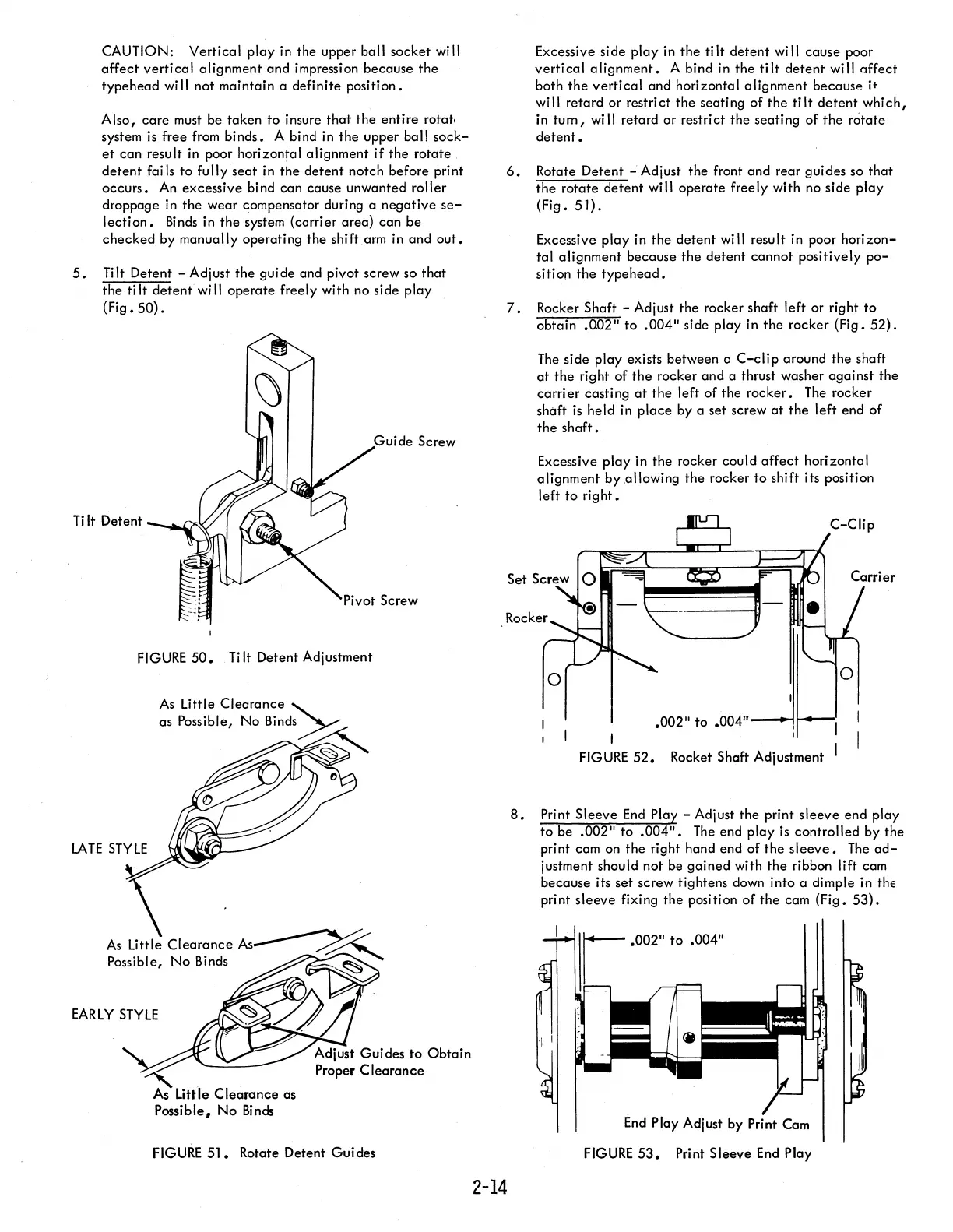
5.
Tilt Detent - Adjust
the
gui de and pivot screw so
that
the ti
It
detent
wi
II
operate
freely with no side
play
(Fig.
50).
Ti
It
Detent
FIGURE
50.
Ti
It
Detent Adj ustment
As
Little
Clearance
As~
Possible,
No
Binds
~
EARLY
STYLE
""
.
As
Little
Clearance
as
Possible,
No
Binds
Adjust Guides
to
Obtain
Proper
Clearance
FIGURE
51.
Rotate Detent Guides
Excessive side
play
in
the
tilt
detent
will cause poor
vertical
alignment.
A bind in the
tilt
detent
will offect
both
the
vertical
and horizontal alignment because H
will retard or restrict
the
seating of
the
tilt
detent
which,
in
turn,
will retard or restrict
the
seating
of
the
rotate
detent.
6.
Rotate Detent - Adjust the front
and
rear guides so
that
the
rotate
detent
will operate freely with no side play
(Fig.
51).
Excessive
play
in
the
detent
will result in poor
horizon-
tal
alignment because the
detent
cannot positively
po-
sition
the
typehead.
7.
Rocker Shaft - Adjust the rocker shaft left or right
to
obtain
.002"
to
.004"
side play in
the
rocker (Fig.
52).
The
side
play
exists between a
C-clip
around
the
shaft
at
the
right of
the
rocker and a thrust washer against the
carrier
casting
at
the
left of
the
rocker.
The
rocker
shaft
is
held in
place
by a set screw
at
the
left end of
the
shaft.
2-14
Excessive
play
in the rocker could
affect
horizontal
alignment
by allowing the rocker
to
shift its position
left
to
right.
FIGURE
52.
Rocket Shaft Adjustment
8.
Print Sleeve
End
Play - Adjust
the
print
sleeve
end play
to
be
.002"
to
.004".
The
end play is controlled by the
print cam on
the
right hand end of
the
sleeve.
The
ad-
justment should not be
gained
with
the
ribbon lift cam
because its set screw tightens down into a dimple in the
print
sleeve
fixing the position
of
the
cam (Fig.
53).
End
Play Adjust by Print Cam
FIGURE
53.
Print Sleeve
End
Play