FIGURE
47.
Ti
It
Tube End Play Adjustment
carrier.
The hole in
the
carrierandrockerwill
make the
tilt
pulley
set
screw
accessible
with a fluted
wrench.
NOTE:
The
height of
the
tilt
sector
gear
is
established
by shimming between
the
gear
and
the
top
of
the
yoke.
The height
is
set
to obtain
the
proper backlash between
the
ti
It
sector
gear
and
the
ti
It
ring
gear.
Be
sure
to
re-install
the
shim if disassembly
is
necessary.
2.
Rotate Shaft
End
Play - Adjust
the
rotate
pu
lIey up or
down
on
the
rotate
shaft so
that
.002" to .004" end
play
exists in
the
rotate shaft
relative
to
the
tilt
tube or yoke
(Fig.
48).
L
"+
• 002"
to
.004"
Wedging
Block
FIGURE
48A.
Gear
Type Tilt
FIGURE
48B.
Gearless
Ti
It
The rotate
pulley
is
secured to
the
rotate shaft by a
wedging block and a set
screw.
The
pulley
set screw
is
accessible
from
below with
the
carrier
centered
over
the
cycle
shaft and
the
shift in
the
upper
case.
After loos-
ening
the
set
screw,
the
grip
of
the
block on
the
shaft
must be broken by rotating
the
typehead
counterclock-
wise manually while blocking rotation of
tf-e
pulley.
This
can be done by inserting
the
3" screwdriver
at
the
rear between
the
notch in
the
pulley
and
the
tape
guide
block.
Be
carefu I not
to
damage
the
tape
or
pu
Iley with
the
screwdriver. DO
NOT
rotate
the
typehead
clock-
wise against
the
tension
of
the
tape
in
an
effort
to
break
the
pulley
loose. Tape
breakage
or
other
parts damage
may
result.
NOTE: The height
of
the
lower ball
socket
is
con-
trolled
by a shim
located
between
the
lower ball socket
and
the
tilt
tube
or
yoke.
The height
relative
to
the
tilt
ring must be
controlled
in order
to
insure proper
op-
eration
of
the
ball
joint.
If
disassembly
of
the
rocker
is
ever
necessary,
the
shim must be
reinstalled.
2-13
3.
Tilt
Ring
- The upper ball socket should be
centered
over
the
lower ball
socket
within
.002".
It
is
adjusted by
moving
thetilt
ring left or right
after
loosening
the
tilt
ring pivot
set
screws. All side
play
of
the
tilt
ring
should be removed by
the
pivot pins while still allowing
the
ti
It
ring
tv
pivot
freely.
If
the ti
It
ring
is
not properly
centered,
the
rotate
posi-
tion of
the
head
can
vary
slightly
as
the
head
is
tilted
to the different
tilt
positions.
This
could
constitute a
portion
of
the
band width in
the
rotate
system.
The
ti
It
ring
is
centered
at
the
factory and
every
effort
should be made
to
maintain its
centered
position.
If
tilt
ring removal or
replacement
is
necessary,
a
feeler
gauge
should be inserted between
the
tilt
ring and
the
yoke to
determine
the
clearance
before
the
tilt
ring
is
removed.
The
tilt
ring should
be
replaced
to
the
same
clearance.
The
tilt
ring
can
easily
be
removed
if
the
machine
is·half
cycled
to
a two
tilt
position.
On
machines prior to
the
gearless
tilt
mechanism,
care
should be
taken
to insure
that
the
ti
It
sector
gears
are
properly meshed whenever
the
tilt
ring
is
installed.
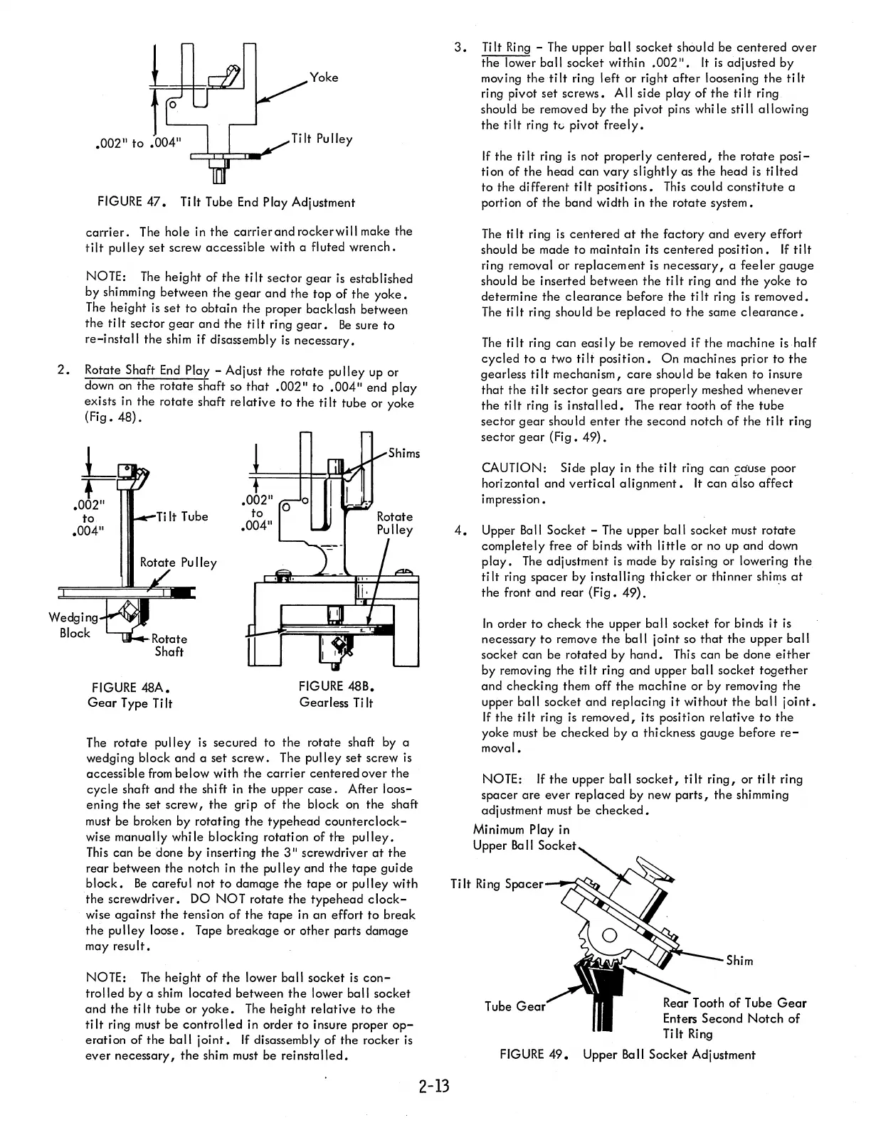
The
rear
tooth
of
the
tube
sector
gear
shou
Id
enter
the
second notch
of
the ti
It
ring
sector
gear
(Fig.
49).
CAUTION: Side
play
in
the
tilt
ring can 9duse poor
horizontal and
vertical
alignment.
It
can
61so
affect
impression •
4.
Upper Ball Socket - The upper ball socket must
rotate
completely free of binds with
little
or no up and down
play.
The
adjustment
is
made by raising or lowering
the
tilt
ring
spacer
by installing
thicker
or thinner
shi~s
at
the
front and rear
(Fig.
49).
In
order
to
check
the
upper ball socket for binds
it
is
necessary
to
remove
the
ball joint so
that
the
upper
ball
socket
can
be
rotated
by
hand.
This
can
be done
either
by removing
the
tilt
ring and upper ball socket
together
and checking them off
the
machine
or
by removing
the
upper ball socket
and
replacing
it
without
the
ball
joint.
If
the
tilt
ring is removed, its position
relative
to
the
yoke must be
checked
by a thickness
gauge
before
re-
moval.
NOTE:
If
the
upper ball
socket,
tilt
ring,
or
tilt
ring
spacer
are
ever
replaced
by new
parts,
the
shimming
adjustment must be
checked.
Minimum Play in
Upper
Be
II
Socket
Ti
It
Ri
ng
C:"",. ..
,r
__
-C
Tube G
FIGURE
49.
Shim
Rear Tooth
of
Tube
Gear
Enters Second
Notch
of
Tilt
Ring
Upper
Be
II
Socket Adj ustment