3.
b.
Late - Position
the
left hand margin release lever:
I.
Laterally so
that
1/32"
of
the rolled pin
on
the
margin release
lever
(Fig. 178).
2.
Radially so
that
the
margin rack will be
hori-
zontal.
Margin Stop Final Stop
a.
Early -
Form
the
lug on the final stop (which
is
welded
to
the
bottom side
of
the
margin rack)
to
ob-
tain
a
clearance
of
.001"
to
.010"
between the
final stop and
the
margin stop with
the
margin stop
pin fully
seated
in
the
extreme left tooth
of
the
mar-
gin
rack.
b.
Late - Position the margin set
lever
stop (Fig. 178)
left
or
right on
the
margin rack so
that
it
will
clear
the
margin stop by
.001"
to
.010" when
the
margin
stop pin
is
fully seated in
the
extreme left hand tooth
of
the
margin
rack.
LH
Margin Release
Lever
FIGUR.E
178.
Margin Rack (Late)
4.
Bell Ringer Bail Adjusting Plate (New) (Fig. 179) - Po-
sition
the
adjusting pldte so
that
the
bellringer
bail
is
parallel
to
the
margin
rack.
Bell Ringer Bail
FIGURE
179.
Bell-Ringer
Bai
I Adjusting Plate
5.
Bellringer Bail Lever
a.
Early
-.
With
the
carrier
positioned
away
from
the
right hand margin stop, adjust
the
bell bail
lever
located
on
the
left
end
of
the
bellringer
bail to
have
.005/1
to
.020"
clearance
with
the
bell
clapper
bell crank
lever
when
the
bai I is
at
rest against
the
bail stop (Fi
g.
180). The bai I stop is
located
at
the
ri
ght end
of
the bai I .
2-52
.005/1
to
.020"
(Adjustment)
(
-~
1~11
\ I
" /
-
-'\
\
FIGURE
180.
Bell Bail Lever (Early Style)
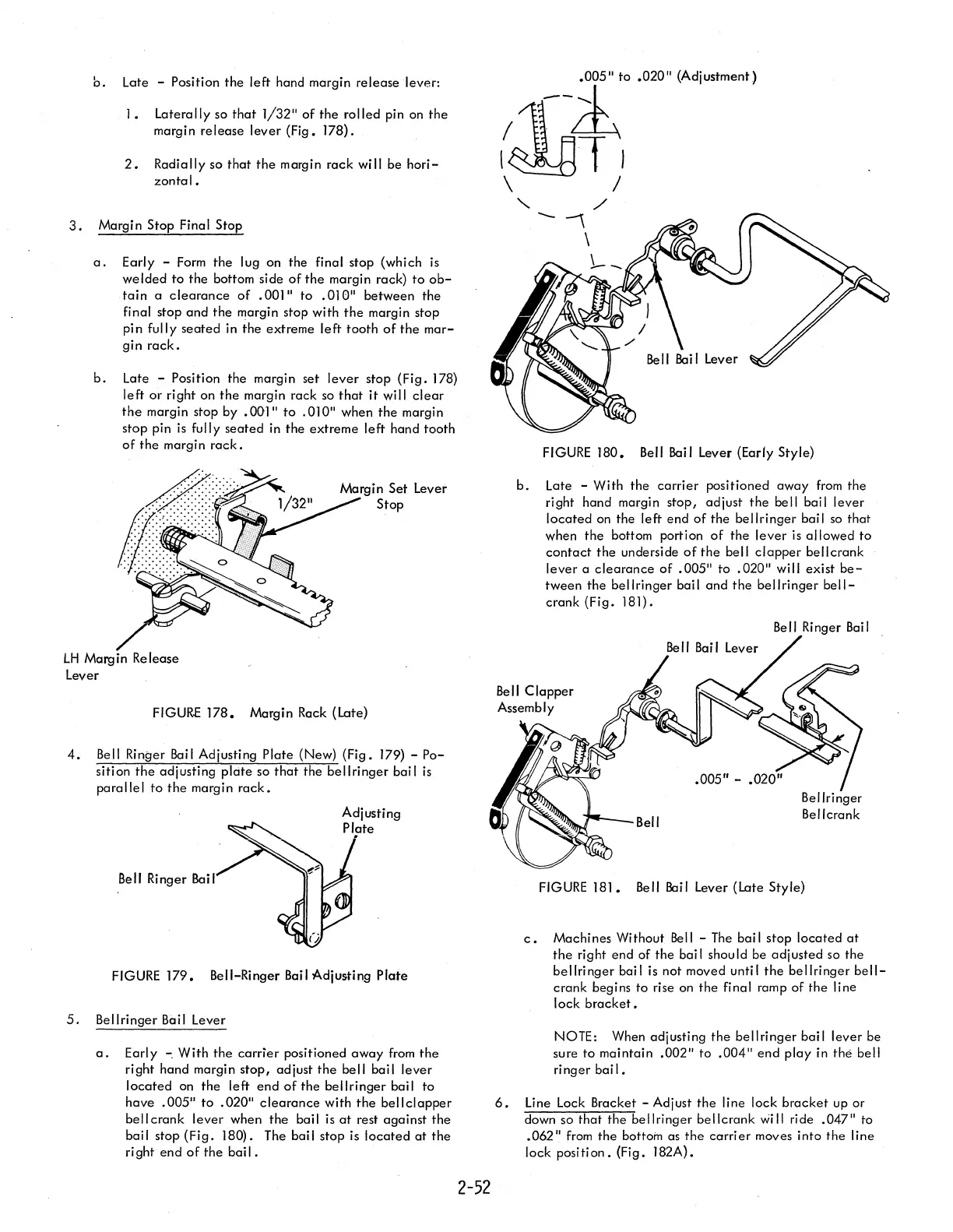
b.
Late - With
the
carrier
positioned away
from
the
right hand margin stop, adjust
the
bell bail lever
located
on
the left end
of
the bellringer bail
so
that
when
the
bottom portion
of
the
lever
is
allowed
to
contact
the
underside
of
the
bell
clapper
bell crank
lever
a
clearance
of
.005"
to
.020"
wi
II
exist
be-
tween
the
bellringer bail and
the
bellringer
bell-
crank (Fig. 181).
Bell Ringer Bail
'~--Bell
FIGURE
181.
Bell Bail Lever (Late Style)
c.
Machines Without
Bell
-
The
bail stop
located
at
the
right end of
the
bail should be adjusted so the
bellringer
bail is not moved until
the
bellringer
bell-
crank begins to rise
on
the
final ramp
of
the
line
lock
bracket.
NOTE: When adjusting
the
bellringer
bail lever be
sure to maintain
.002"
to
.004"
end
play in
the
bell
ringer
bail.
6.
Line Lock Bracket - Adjust
the
line lock
bracket
up or
down so
that
the
bellringer
bellcrank
will ride .047/1 to
.062/1
from
the
bottom as
the
carrier
moves into
the
line
lock position. (Fig. 182A).