10.2
.002"
- .
005"
clearance
between
the
-5
latch
and
its
stop.
(Shou
Id
reset
at
same time as positive
lat-
ches) .
10.3
Half
cycle
a
zero
rotate
character
and
adjust
the
rotate
link so
that
the
pointer
on
the
rotate
arm
matches
the
# 1
scribe
on
the
Hooverometer, when
the
Hooverometer is depressed
against
the
damper spring.
10.4
Match
the
home
detenting
with:
a.
The
negative
5
latch
selected.
b.
All positive latches
selected.
10.5
The
detents
should
seat
fully with no side
play.
10.6
2 Ibs. with a
-5
character
half-cycled.
10.7
Adjust
the
Rotate
Arm
Eccentric so
that
a
half-cycled
-5
se
lecti
on
matches a ha
If-cyc
led home se lecti
on.
10.8
Adjust
the
print shaft timing so
that
the
detent
enters
and
leaves
all
rotate
positions without rubbing on
the
ski
rt.
10.9
The Damper Spring must not bind on
the
Paper Bail
Stud.
Adjust
the
Damper Spring Stop
1/8"
-
1/16"
from bottom of
the
spring.
A
-5
selection
should
ful-
ly compress
the
Damper
Spring.
10.10
COMPENSATOR WEDGE
Overcompensation
may
occur
whenever
(a)
the
system
receives
a sudden shock which unloads
the
rotate
arm,
(b)
the
detent
enters
the
wrong
type
head
notch prior
to
rotate
comp leti
on,
(c)
the
detent
enters
the
wrong
notch
after
rotate
completion.
If
the
wedge
drops too
far (overcompensateds)
check:
a.
Excessive head
play.
b.
Shift timing adjustments.
c.
Fine timing
and
skirt
clearance
#10.8.
d.
Binding
or
sticking
rotate
spring.
e.
Bi
ndi
ng
rotate
eccentri
c arm shou Ider .
f.
Binding or sticking damper spring
#10.9.
g.
Popping
selector
latches
due
to
maladjusted
latch-links.
h.
Fi
Iter shaft
timing.
i.
Binding
typehead
due
to
the
ti
It
ring
spacer
being
off-center.
j.
Rotate spring tension
'#10.6.
If
the
wedge does not drop
far
enough
(undercompen-
sates)
check:
a.
Wedge is
dirty,
oi Iy, or
serrated.
The wedge
should
be
cleaned
with
IBM
cleaning
fluid.
If
the
wedge becomes scored
or
serrated
it
may
be
reversed.
b.
Rotate arm
eccentri
c adj ustment #
10.7
.
10.11
Selection
System
Check
(See
Section
13.0).
10.12
Print Magnets (See
Section
14.0).
10.
13
Form
the
padd
Ie
so
that
home
detenti
ng
matches
the
-4
detenting
.
10.14
Adjust
the
Rotate
Arm
length so
that
a
-.3
character
4-15
detents
the
same
as
a +5
character.
10.15
S.H.
MAL-SELECTION
Random
mal-selection
may result
if
the
C-5
contacts
open during a print
operation.
What
actually
happens
is
that
a
given
pulse
of
be-
tween 30 and 40 milliseconds
is
placed
on
the
print
magnets,
the
armature
is
attracted,
and
trips
the
cy-
cle
clutch
mechanism. At this period in
time,
due
to
some
malfunction,
the
C-5
contact
opens.
This,
be-
ing
an
interlock
contact,
interrupts
the
pulse
to
the
print
magnets.
The
cyc
Ie
clutch
has
been
activated
and
the
machine
will
take
a
cycle;
however,
the
in-
tended
character
wi
II
not
be
selected:
Either
selec-
tion
of
an
extra
cycle
or
mal-selection
will
occur
since
the
armature has restored
and
has not
selected
the
proper
latches.
One
specific
instance
of
the
C-5
contact
breaker
opening during a print
operation
is
when
the
C-5
con-
tacts
are
adjusted
too
far
to
the
right.
The
C-5
contacts
are
operated
by
a cam
follower.
The
follow-
er
is
curved until
it
reaches
a
flat
portion which in
turn
operates
the
contact
operating
strap.
If
the
con-
tacts
are
adjusted
too
far
to
the
right,
they
will
con-
tact
the
curved portion
of
the
cam follower
and
will
open
erroneously.
10.16
S
,H.
MAL~SELECTION
Random
parity
and
selection
errors
can
be
caused
by
loose
or
broken
selector
latch
extensions.
A
change
has
been
processed
to
improve
the
riveting process
used
to
attach
the
'latches
and extensi ons (see
13.4).
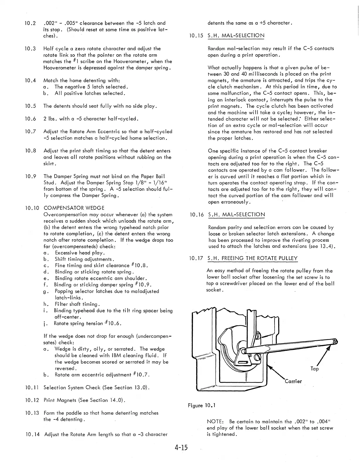
10.17
S.H.
FREEING
THE
ROTATE
PULLEY
An
easy
method
of
freeing
the
rotate
pu
lIey from
the
lower
ball
socket
after
loosening
the
set
screw
is
to
tap
a screwdriver p
laced
on
the
lower
end
of
the
ba
II
socket.
~'----------~~'
Figure 10.1
NOTE:
Be
certain
to
maintain
the
.002"
to
.004"
end
play
of
the
lower
ball
socket
when
the
set
screw
is
tightened.

 Loading...


